Example Builder Warranty
Disclaimer – this and subsequent articles on this subject are not intended to be legal advice, merely an example for discussions between you and your legal advisor.
I cannot express strongly enough how important to both builders and their clients to have a written warranty in any agreement.
WARRANTIES: There is no warranty applicable to the building and is expressly in lieu of all other warranties available under any State or Federal laws, expressed or implied, including any warranty of all labor, material, product and taxes will be paid for and there will be no potential lien claim against Purchaser’s property upon completion of the work and following final payment by Purchaser to Seller.
Products supplied by third party suppliers, manufacturers and sub-contractors to the project are warranted only to the extent that the suppliers and manufacturers of those products provide a warranty.
In the event that a defect is discovered in one of these products, Seller will assist Purchaser in securing repair or replacement of these products under the warranty provided by the third party supplier or manufacturer. Warranty work is work which was correctly and completely done initially, but becomes non-operational or dysfunctional following occupancy or use by Purchaser. No retainage or holdback will be allowed for warranty work.
Seller expressly warrants to the original noncommercial purchaser(s) and only the original purchasers.
That if any part of a Seller constructed post frame building, as covered by this warranty, proves to be defective due to materials or workmanship, under normal use and service, for two (2) years, that defective part will be repaired or replaced, subject to the terms and conditions contained in this Warranty.
Seller hereby assigns to Purchaser all rights under manufacturer’s warranties. Defects in items covered in manufacturer’s warranties are excluded from coverage of this limited warranty, and Purchaser should follow the procedures in the manufacturer’s warranties if defects appear in these items.
For ten (10) years.
Any solid sawn or glu-laminated (pressure treated to a minimum UC-4B) structural columns that fail due to decay or insect damage, unless said column has been exposed to animal wastes.
The original building roof structure, if damaged directly by snow loads because of the failure of any prefabricated roof truss or trusses to meet design specification. Subjecting your roof system to greater loads than those set out on the face of this Agreement, any unspecified ceiling loads, or modifying the trusses in any way voids all Warranties.
Any major structural defects which are defined as being an actual defect in a load-bearing portion of the building which seriously impairs its load-bearing function to the extent that the building is unsafe. For purposes of this definition, the following items compromise the structure of the building:
- Load bearing columns,
- Floor or ceiling joists,
- Beam, trusses and rafters.
For Two (2) Years:
Any roof leaks due to defects in material or workmanship, expressly excepting where the building has been connected to an adjoining structure, in roof valleys, or at roof slope changes to which cases, no warranty applies.
Any other building parts which prove to be defective in material or workmanship.
This warranty period shall commence on the date of the acceptance of the building by the Purchase or Purchaser’s occupancy of the building, whichever comes first.
This warranty contained wherein is void in situations where:
- Installation is not made in accordance with the instructions supplied by Hansen Buildings.
- The actual operation or use of the product varies from the recommended operation or intended use.
- There is a malfunction or defect resulting from or worsened by misuse, negligence, accidents, lack of or improper performance of required maintenance by the original purchaser.
- The building is altered or added onto, unless by Seller.
- Seller is not notified within twenty four (24) hours of problems due to snow loads.
- Purchaser fails to take timely action to or damage.
- Anyone other than Seller’s employees or agents or subcontractors have been on the building roof.
- Purchaser fails to make final payment per terms of sale.
Equipment such as fans, HVAC, gutters, downspouts, walk door locksets, other equipment not manufactured by Seller, site work, concrete, doors, windows, interior finishes, mechanical or electrical systems are excluded from this warranty.
The Purchaser expressly agrees to fully and timely pursue all available remedies under any applicable insurance agreement before making claim under this warranty.
In the event Seller repairs, replaces or pays the cost of repairing or replacing any defect covered in this warranty for which Purchaser is covered by insurance or a warranty provided by another party. Purchaser must assign proceeds of such insurance or other warranty to Seller, to the extent of the cost to Seller, of such repair or replacement.
Any claims for defects under warranty must be submitted in writing to Seller within the warranty period and promptly after discovery of the claimed defect, describing the defect claimed and date of building completion, before Seller is responsible for correction of that defect. Written notice of a defect must be received by Seller prior to the expiration of the warranty on that defect and no action at law or in equity may be brought by Purchaser against Seller, for failure to remedy or repair any defect about which Seller has not received timely notice in writing.
Purchaser must provide access to Seller, during normal business hours to inspect the defect reported and, if necessary, to take corrective action. A reasonable time should be allowed for inspection purposes. If, after inspection, Seller agrees, at its sole option to repair or replace only the defective materials or workmanship within the first three months from date of building completion at NO COST to the Purchaser. Thereafter Seller shall assume the cost of material and labor for any warranty work upon advance payment by the Purchaser of a one hundred dollar service payment for each incident under this warranty. The obligation of Seller, under this warranty, shall be performed only by persons designated and compensated by Seller for that purpose, and is subject to all other provisions of this warranty.
The provisions of this Warranty are the full and complete warranty policy extended by Seller, and are expressly in lieu of all other warranties, expressed or implied, including any warranty of merchantability or fitness for a particular purpose. These warranties may not be transferred or assigned. The liability of Seller shall not exceed the cost to Seller for repairing or replacing damaged or defective material or workmanship, as provided above, during the warranty period.
THE WARRANTY STATEMENTS CONTAINED IN THIS LIMITED WARRANTY SET FORTH THE ONLY EXPRESS WARRANTIES EXTENDED BY SELLER FOR ITS BUILDING AND THE PROVISIONS HEREOF SHALL CONSTITUTE THE PURCHASERS EXCLUSIVE REMEDY FOR BREACH OF THIS WARRANTY. IN NO EVENT WILL SELLER BE LIABLE TO THE PURCHASER FOR INCIDENTAL OR CONSEQUENTIAL DAMAGES OF ANY KIND FOR BREACH OF AN EXPRESS OR IMPLIED WARRANTY ON THE BUILDING; PROPERTY DAMAGE, PERSONAL INJURY , OR ECONOMIC LOSS IF OCCASIONED BY SELLER’S NEGLIGENCE, EVEN IF SELLER HAS BEEN ADVISED OF THE POSSIBILITY OF SUCH DAMAGES.
Some states do not allow the exclusion or limitation of incidental or consequential damages, so the above limitations or exclusions may not apply to you. This warranty gives you specific legal rights and you may also have other rights which vary from state to state.
Purchaser shall promptly contact Seller’s warranty department regarding any disputes involving this Agreement.
Seller and Purchaser agree that this limited warranty on the building is in lieu if all warranties of ability or workmanlike construction or any other warranties, express or implied, to which Purchaser might be entitled, except as to consumer products. No employee, subcontractor, or agent of Seller has the authority to change the terms of this warranty.
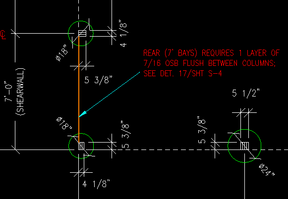
 This leaves “in hangers” between trusses as your only viable (and practical) design solution.
 Your best column is going to be a glulam, hands down.
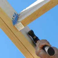
 Your stone wainscot will require sheathing and I would not personally install LP siding without sheathing. An Omnidirectional water resistant barrier should be placed on exterior side of your sheathing (under siding).
 1) Why would you want to use your own posts, when we have available and affordable stronger glulaminated columns than anywhere else in America?
  DEAR POLE BARN GURU: I am getting ready to pour a concrete slab in my 24’x30′ pole barn. I calculated the thermal contraction along the 30′ length to be just over 1/8″. Would it be a good idea to install a foam sill sealer type material onto the inside of the grade boards to accommodate any thermal movement of the slab? DAVID in WESTFIELD
  DEAR POLE BARN GURU: O great pole barn genius, what would I want to store an RV, also be at least a 2 car garage, and workshop, with a couple finished rooms for living quarters? What’s that beast called, and what should I budget for it low/high in KY? KIM in PAYNEVILLE
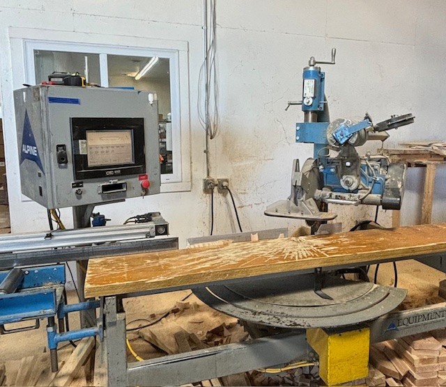
 The following is a summary of the IRC requirements for wood Trusses (capitalized terms are defined by ANSI/TPI 1-2014, National Design Standard for Metal Plate Connected Wood Truss Construction, Section 2.2, published by the Truss Plate Institute (TPI)):
 · Truss bracing requirements are found in Section R802.10.3. This section requires Trusses to be braced to prevent rotation and to provide lateral stability. It allows the bracing requirement to be specified in the construction documents or on the individual Truss design drawings. It also states, “In the absence of specific bracing requirements, Trusses shall be braced in accordance with accepted industry practice such as the SBCA Building Component Safety Information (BCSI) Guide to Good Practice for Handling, Installing & Bracing of Metal Plate Connected Wood Trusses.” See the Building Component Safety Information Book (BCSI), which has the above reference guide as a section. (https://www.sbcacomponents.com/bcsi)
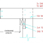 DEAR POLE BARN GURU: On a double truss system with 12′ o/c how do you do the gable ends? MICHAEL in KALAMAZOO
  DEAR POLE BARN GURU: Roof only pole building, does flashing go in the roof valley on the dormer? STACY in CARRIERE
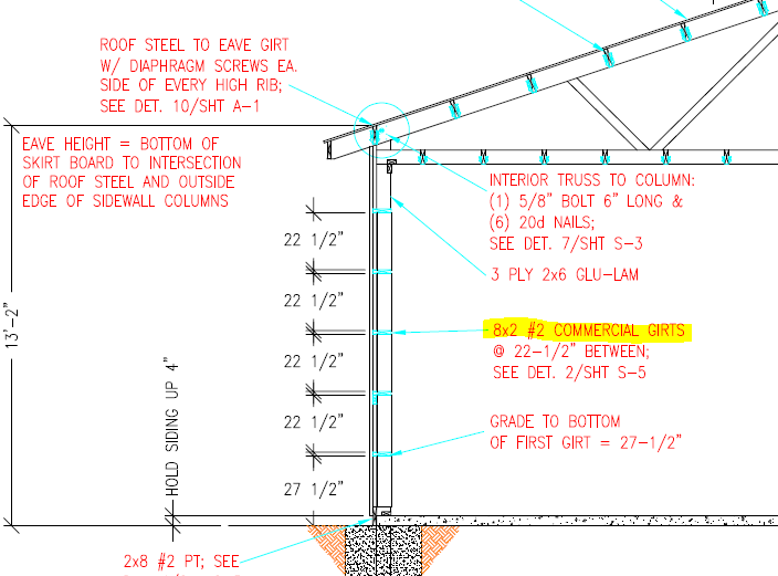
  DEAR JOHN: If using anything other than structurally rated, through-screwed steel roofing, then your answer is most likely yes. With through screwed steel roofing, provided you have utilized appropriately sized fasteners, at correct spacing, then sheathing would only be a requirement if shear loads are greater than what your roofing’s shear load capacity is. In most instances fasteners at top and bottom of panels should be something such as Leland Industries ‘diaphragm screws’ on both sides of each high rib. For extended reading on these screws, please read:
  Reader BRAYTON in NORTHEAST WASHINGTON writes: “I’ve been previewing your website and am glad I found it!
 Mike the Pole Barn Guru writes:
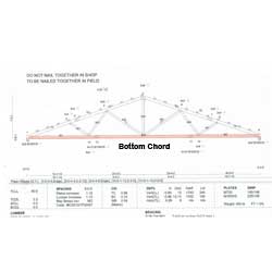 DEAR LYNNE: Transportation can often be a limiting factor. In order to avoid pilot cars and over width permits, maximum truss height is limited to 102″ (8’6″). A 50′ span, 4/12 slope truss will normally be roughly 108″ tall, plus any overhang “tails”. So, this would entail an over width permit. Now most truss companies purchase year-long over width permits for their trucks, so this cost is negligible. Most states do not require pilot cars, unless loads are 12 foot or greater in width. This allows for 60 foot span trusses to be hauled without expensive pilot vehicles. As to procurement, while you will pay more per lineal foot of truss as spans increase, you will also need fewer trusses. For an agricultural building, I always encourage clients to build as large as they can economically justify and have space to build on, as it will never be too big. Keeping your building length to three times building width will also help with your budget, as these ratios are typically within shear load carrying capabilities of properly fastened steel roofing and siding.
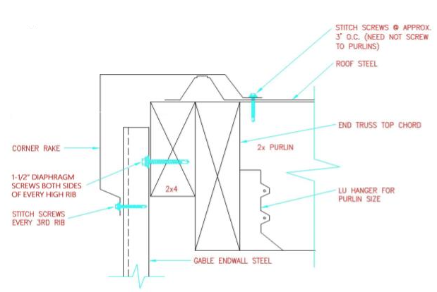
 DEAR POLE BARN GURU: Building a 50x36x12 pole barn with 4:12 roof pitch. Attic space will be unconditioned with blown in cellulose insulation in ceiling and batten on walls. Attic will be vented with soffit and ridge vent. Walls will have exterior house wrap under metal panels. Question is, what to put under the roof panels? Just a vapor barrier or a dual purpose vapor/radiant barrier? I hear different opinions on placing radiant barrier under roof. STEVEN in SUGAR LAND
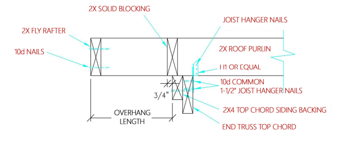
 DEAR CODY: In my humble opinion, foundation walls for post frame buildings defeat much of the cost savings with little or no added benefit. I will now step off my soap box….
 DEAR POLE BARN GURU: Can any of your buildings be built where the back half of the building is suspended on poles…..because the ground slopes downhill? What about zoning? Do you check with my county to find out whether or not I can have a building? DAVID in WESTMINSTER
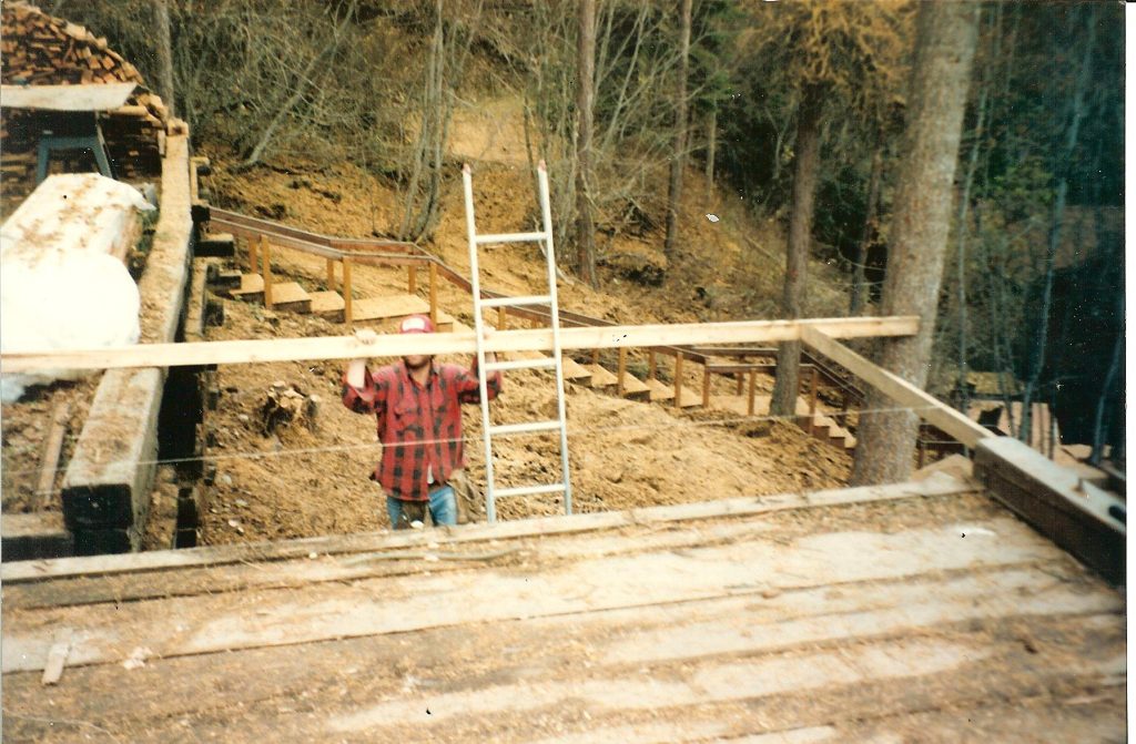
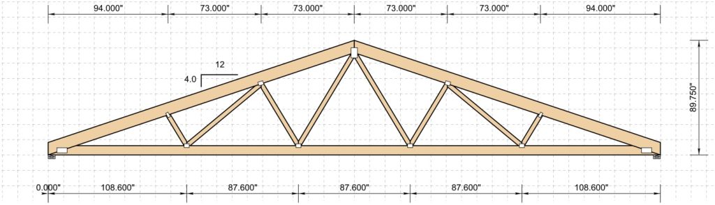
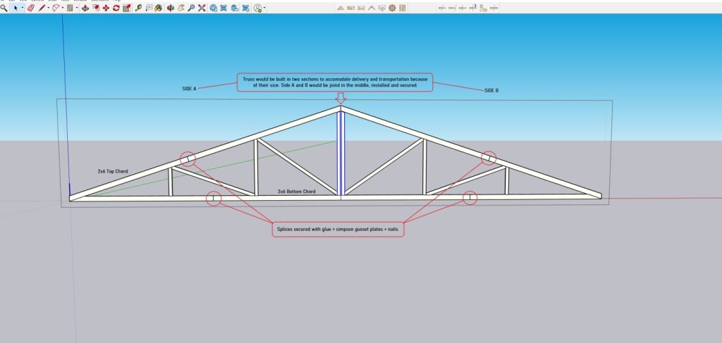
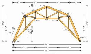
 I spent two decades in management or owning prefabricated metal connector plated wood truss plants. In my humble opinion – attempting to fabricate your own trusses of this magnitude is a foolhardy endeavor, for a plethora of reasons:
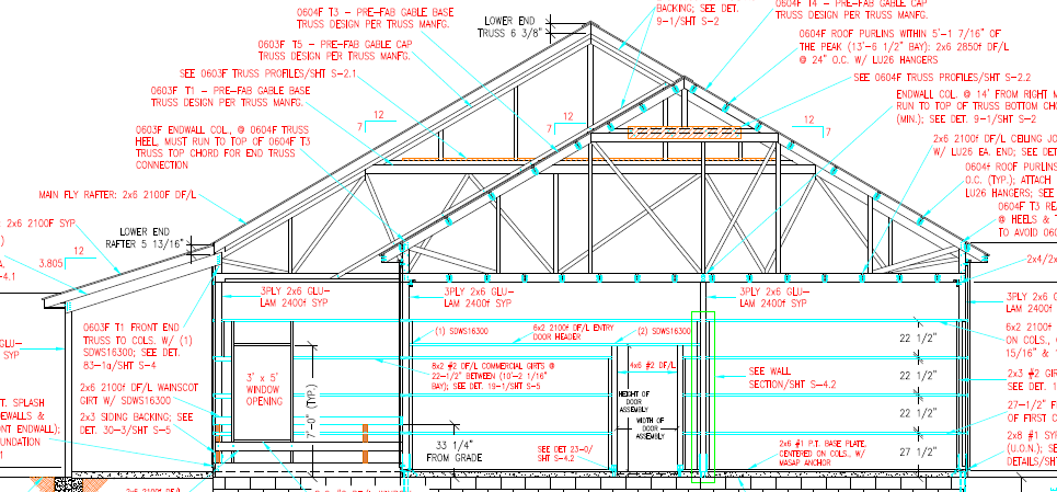
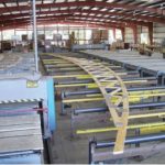 DEAR PETER: Unless your building has a very wide clearspan, or some huge dead loads (or perhaps a bonus room) a three ply truss seems strangely unusual. You might want to reach out to other possible truss manufacturers to see if you can get a two ply design. While I have seen three ply trusses notched in 4-1/2 inches approved by engineers, if indeed this is your final truss design solution, you should confirm connection adequacy by reaching out to your building’s Engineer of Record.
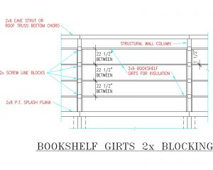
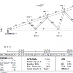
 We typically would use 2×6 #2 on edge for these recessed (between truss pairs) roof purlins. Here are the calculations:
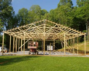 DEAR POLE BARN GURU: I am planning to build a pole barn 36×40 on 10’ centers with heavy duty steel roof trusses on 6×6 posts. The wall height will be 10’ and I would like to have 3’ faux stone for siding at the bottom with the rest of the siding hardi plank cement board. Would the weight be too much for a traditional pole barn style framing? NICK in CROSBY
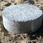 DEAR FRAN: Our engineers typically detail bottom of roof supporting column holes with an eight inch thick concrete footing mono poured with 10 inches of concrete up each side of columns, resulting in a total depth of pour of 18 inches.
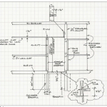
 Anyhow, back on point, there were an incredible number of people totally willing to undertake erection of their own pole barns. Even more amazing is – any of them turned out! We provided absolutely no instructions and “plans” (I use this term lightly) were drawn by hand on a few sheets of 8-1/2” x 11” white copy paper.
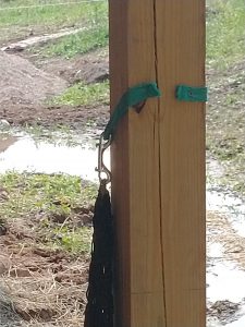 DEAR LEVIA: In most instances a 4×6 #2 will be stronger than a 6×6, however switching out columns should only be done with approval from your engineer who sealed your building plans.
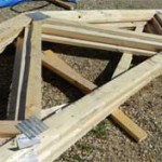 DEAR POLE BARN GURU: 2 x 4 Truss spacing question, how long do you advise to build a Pole barn with 15pcs of 2 x 4 x 24′ engineered trusses? 🙂 The fires got 8 of them so I’m refiguring my length, but wanted some help on the truss spacing? Thanks, MARSHALL in PORTLAND
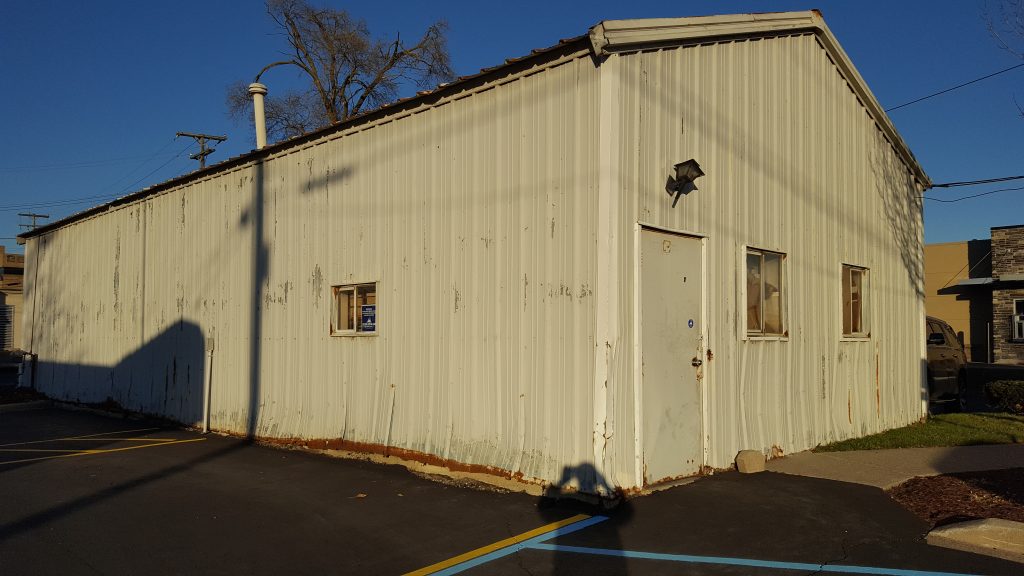
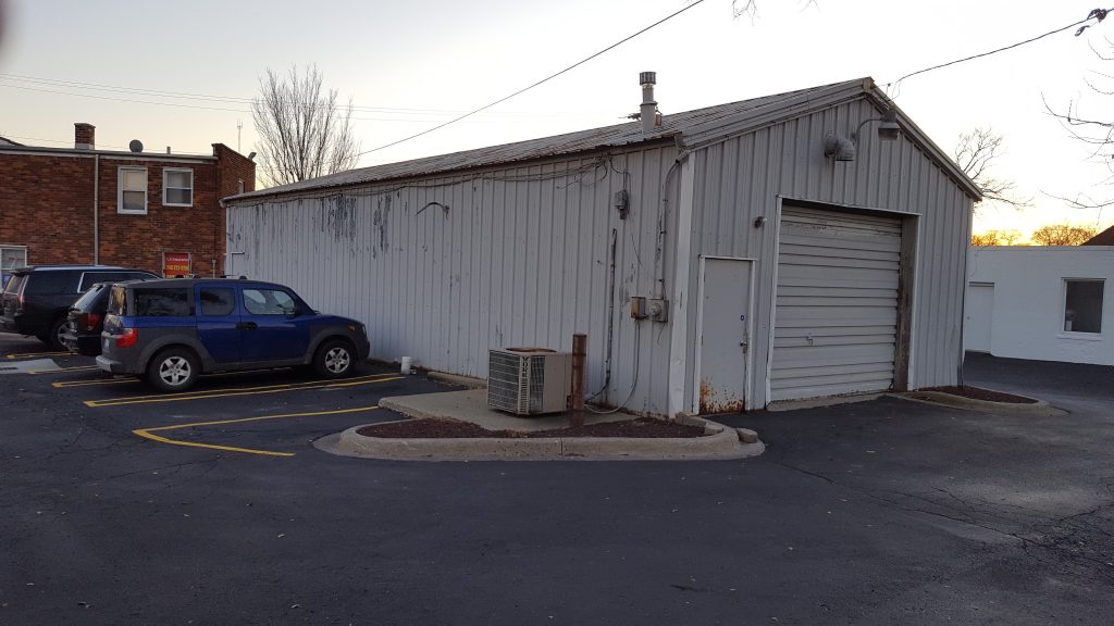
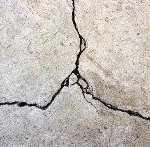 DEAR POLE BARN GURU: I’m working on a fire loss to a post frame building that was converted to multi-unit apartments. The building shell is post frame on slab with interior walls framed. My question is could we demo the building saving the slab rebuild utilizing standard residential stud wall and truss framing. Thanks CHRIS in FLOYDS KNOBS
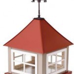 DEAR POLE BARN GURU: What base size and height is correct for a cupolas for a 32’ wide by 36’ long by 35-40’ high with a 10 over 12 pitch roof? Thank you for your answer. NANCY in SPENCER
 DEAR ERIC: 40 years ago I provided a post frame building kit package for a tire dealer in Pahrump!
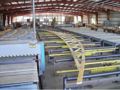
 Mike the Pole Barn Guru writes:
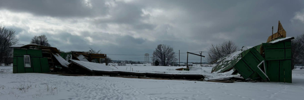
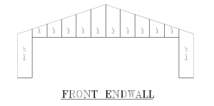 Your hay barns happen to be a worst case scenario when it comes to sound structural design of a post frame building:
 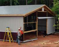 If hiring a contractor to perform any sort of work on your property thoroughly vet them (
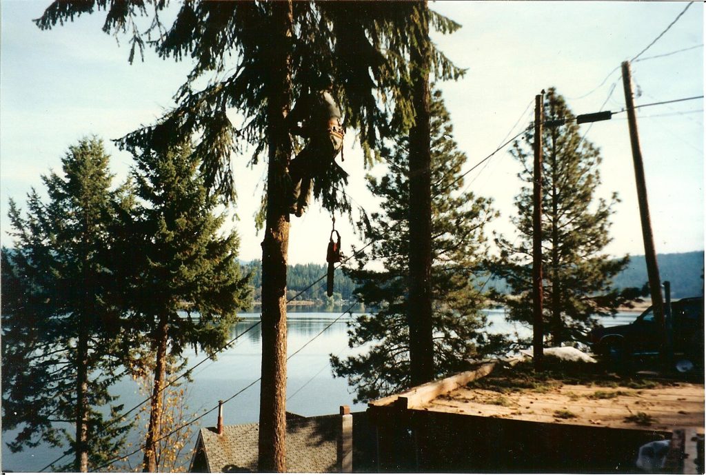
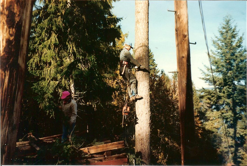
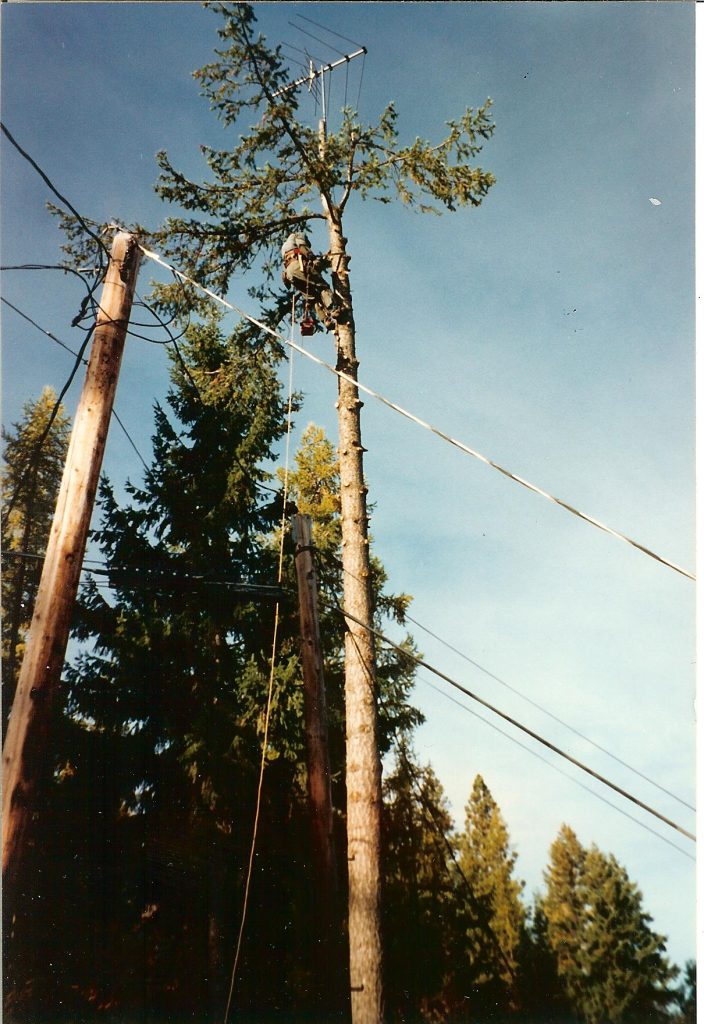
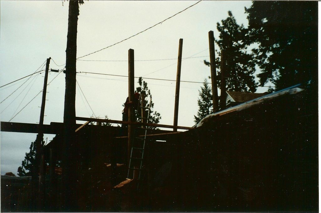
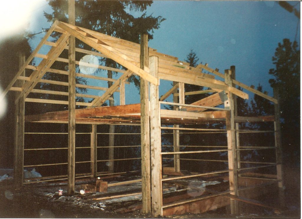
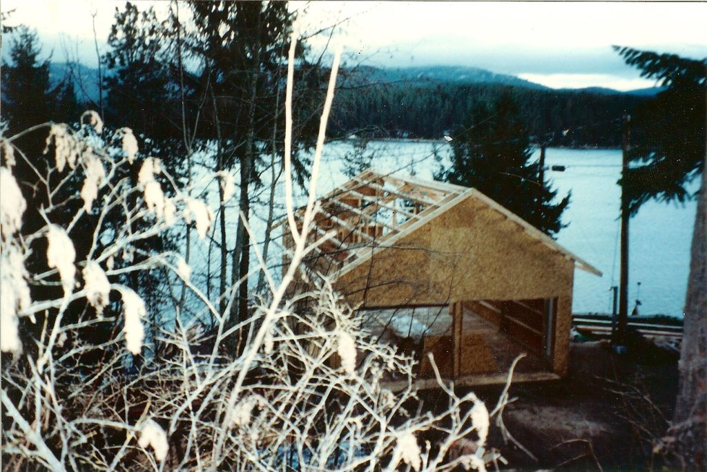
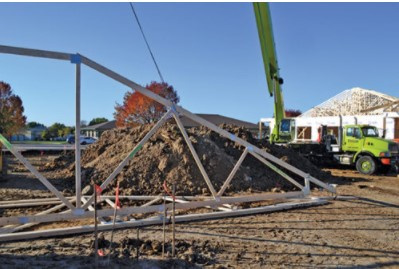
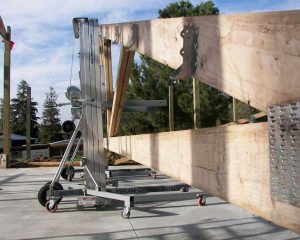 I am all for building sections on terra firma and raising them up with winch boxes. I have done it more than once, with trusses spanning up to 80 feet. Although probably not involving any new world order conspiracy, you are correct in this being a well-kept secret. While I have not personally tried mounting winches directly to columns without boxes, I know builders who have merely mounted a pulley wheel to column tops and then affixed winches directly to column faces and ground level with duplex nails, so your idea is not far-fetched. Each bay of your building weighs under 2000 pounds total (or less than 500 pounds per column) so it could be as simple as using say four or so of your five inch long Simpson screws for attachment as they will support over 250 pounds each and this would give a high degree of safety.
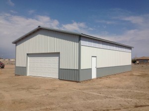 DEAR POLE BARN GURU:
  DEAR RACHEL: Your question leads me to believe you do not have structural plans for your building. Said structural plans should be prepared by a Registered Design Professional (RDP – architect or engineer) who can expertly determine structural adequacy of all building components, as well as proper connections.
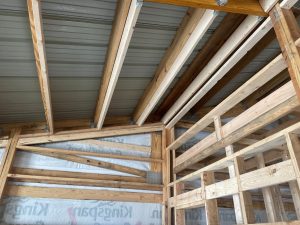
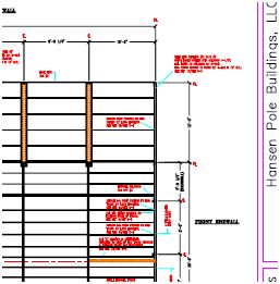
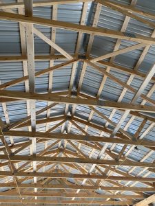 DEAR DOUGLAS: Your trusses should be shown on your building’s engineer sealed plans. You can provide these to any prefabricated wood roof truss manufacturer (or the ProDesk at your nearby The Home Depot) to get a quote delivered to your building site. If it was my own personal building, it would have a single truss on each endwall, and a double truss every 10 feet bearing directly upon wall columns. I would place 2x purlins on edge between truss top chords, using engineered steel joist hangers to support each end.
 DEAR POLE BARN GURU:
 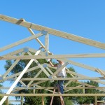 DEAR POLE BARN GURU:
 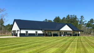 2019’s average home had 2594 square feet of finished space and a sales price of $485,128. Without lot costs, general contractor’s overhead and profit actual construction costs were $296,652 ($114 per square foot).
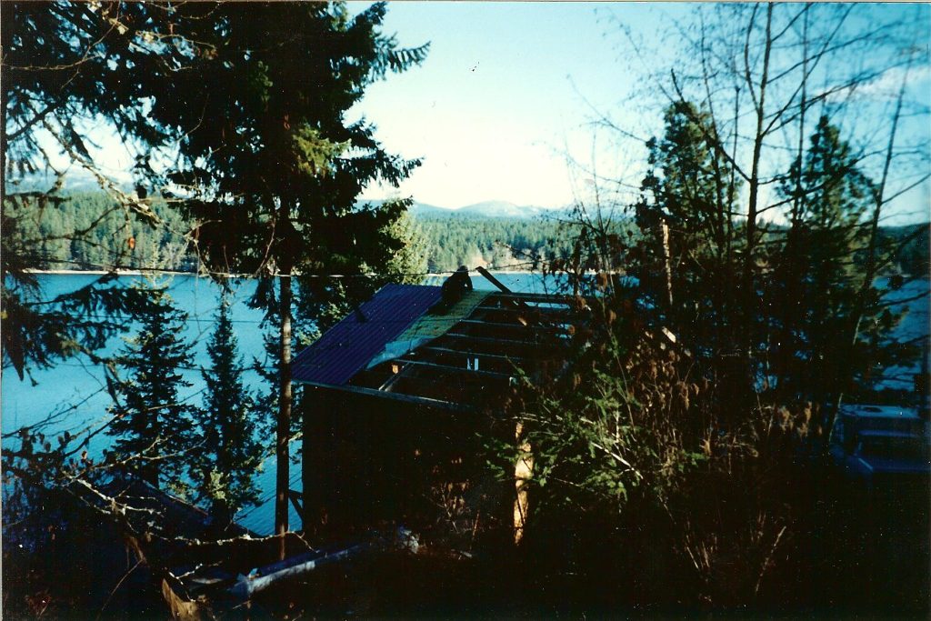
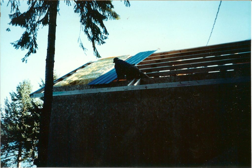
 He was furious because he did not want heavy equipment, like a crane, run across his yard to lift his roof up. Luckily we were able to talk him down and assured him when he came home from work his roof would be up in place and there would be no tire tracks.
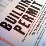 DEAR TINA: Thank you for your interest in a new Hansen Pole Building. You will need to complete a building department questionnaire which provides us the necessary load information we need to properly design your structure, with that we guarantee our third-party engineered plans will pass a structural approval. Usually your plans will be sent to you in seven to 10 days after you have electronically approved your documents.
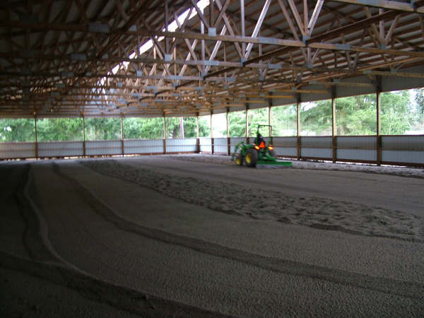
 DEAR LEE: We only provide building plans along with an investment into a Hansen Pole Buildings post frame building kit package. We firmly believe every post frame building should be structurally designed and plans sealed by a Registered Professional Engineer. Whether stamped drawings are required or not, if an engineer didn’t design it, who did? It is frankly just not worth risking your life or your valuable possessions in an attempt to save a few dollars.
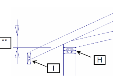
 DEAR VICKIE: Considering it is only 375 miles from Browns Valley to Hurley, you are almost local! Hansen Pole Buildings provides post frame buildings in all 50 states (yes – even Alaska and Hawaii), so Wisconsin is not an issue.
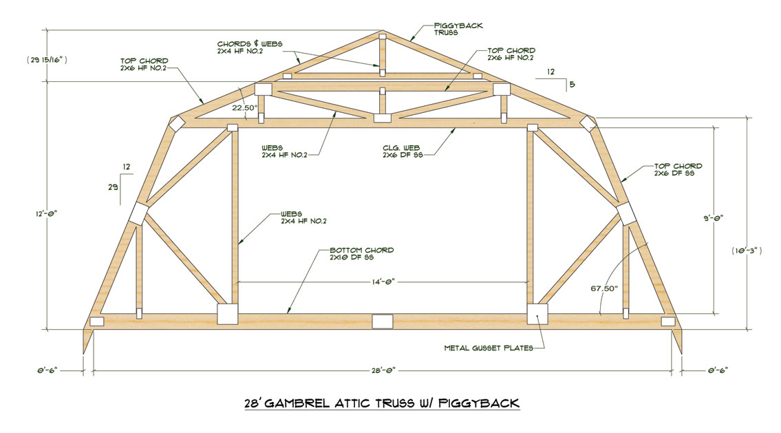
 This very same adage holds true with those punting at their own building design….engage a trained professional. Or even better, a complete post frame building package structurally designed by a trained professional. And when I talk about “trained professional” in this context, I mean plans sealed by a Registered Design Professional (RDP – architect or engineer) specifically for your building on your property.
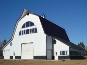 In many cases it may be possible for an engineered truss repair to be made, to upgrade load carrying capacity of truss bottom chords to a minimum of five psf. I’m sorry to say, this is not free. Truss company’s engineer will need to put his or her license on the line in designing a “fix” for trusses designed for a load other than is now intended. It’s not same as designing original trusses. If you think about it, redesigning and augmenting something you have built, is always more time consuming (and brain challenging!) than first time around. His time and expertise are not without a charge. It’s not usually “much”, like a couple hundred dollars. Then there is cost of materials to do repairs. This will be final out-of-pocket expense if you are doing truss repairs yourself. If not, a contractor’s charge must be added. All totaled, it could run you anywhere from a couple hundred dollars to over a thousand or more.
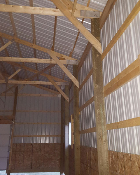
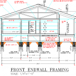
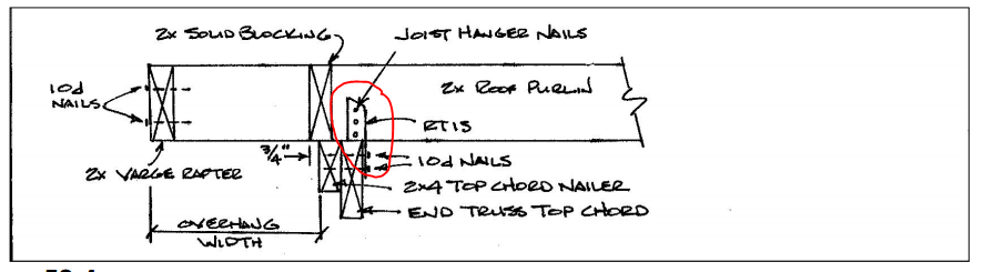
 DEAR RANDALL: Typically each gable endwall would have just a single end truss. Some possible exceptions would be if you were designing to be able to extend building length in future, or for airplane hangars where there exists added strength requirement in order to support weight of a door.
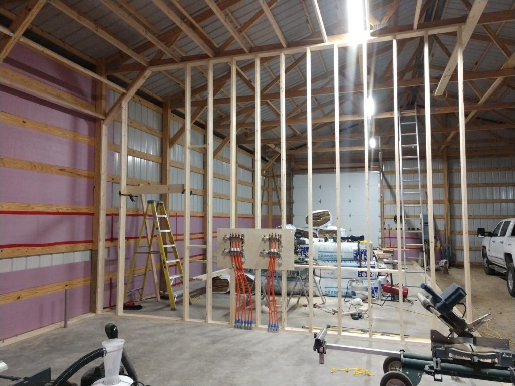
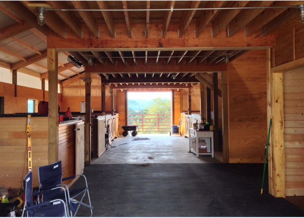
 DEAR DAVE: I will interpret your “rafters” to be Midwestern casual term for roof trusses. If so and properly designed to support required loads, trusses could be placed every four feet. In order to support roof steel, purlins would need to be laid either across top of, or joist hung in between roof truss top chords.
  DEAR POLE BARN GURU:
  I have a construction question… I
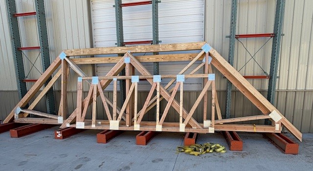
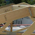
 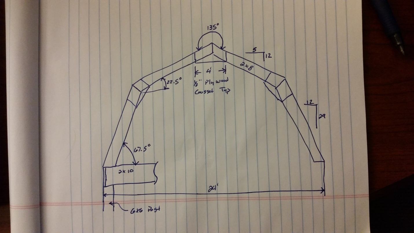 Gambrel style rooflines are often enticing, they offer the feeling (however not the reality) of getting added space for free. Building your own gambrel barn trusses might appear on the surface like a way to make this even a greater savings.
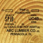
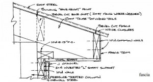
 DEAR RALPH: From Chapter 14 of the Hansen Pole Buildings’ Installation Guide: Using a minimum 5/16” galvanized staple, staple through insulation to eave purlin top. As an alternative to staples, 1” galvanized roofing nails (with the big plastic washers) also work well.
 Post frame buildings also work as a system, so individual components or connections might possibly be adequate, however the entire building fails due to a weak link. This is why I always, always (did I say always) recommend ONLY to invest in a building which is designed by a registered design professional (RDP – engineer or architect) – especially for your particular site.
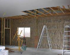 DEAR POLE BARN GURU: I have a 42 x 60 with insulation in walls and roof, 26 gauge metal, wood trusses, 10 feet o.c. with 2 x 6 purlins. I do furniture and cabinet work and love the insulation but would like to add the white metal ceiling, to help with the heating, cooling, and lighting. Can I add trusses in between existing ones, and build them underneath the purlins? If so can the white metal span 5 feet for a metal ceiling? CHARLES IN BUTLER
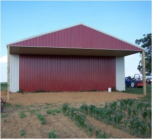 My response: Actually in the hundreds of buildings we have provided with carports, you are quite honestly the first person who has ever brought forth any of these issues as being challenges. Your bringing this to our attention is greatly appreciated.
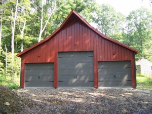
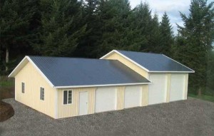
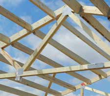 As pole buildings have gravitated from the farms of the 1950’s into the mainstream of popular construction, their owners have been looking for more appeal than what was offered by the average tractor shed.
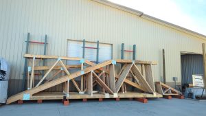 Prefabricated roof truss drawings (provided by the roof truss manufacturers) give the recommendation for how the truss designer feels the trusses should be braced, however the ultimate design of the truss bracing system, is the responsibility of the building designer (registered design professional – engineer or architect).
 The post-frame industry has grown steadily in North America, gaining more and more widespread application in the past 100 years. Yet, many people still wonder, “What is post-frame construction?”


