How Far Can a 2×6 Purlin Span?
Reader WILL in COMFORT writes:
“How far can a 2×6 purlin on a 6:12 sloped roof span?”
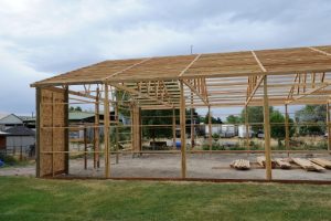 The following describes 2×6 SYP #2 purlins spanning a 14′ bay, with an on-center spacing of 24″ (sf).
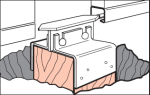
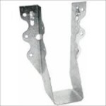
Purlins are recessed between rafters with their top edges flush with rafter top edges. Purlins are mounted to rafters with Simpson Strong-Tie LU-26 joist hangers at both ends.
Effective simple beam span length (le) will be taken as 165.
Applied loads
Dead load, D[
Dpurlin: dead load from weight of purlin itself
Dpurlin = purlin density × ((b × d × le) / (sf × l))
Purlin density found via NDS Supplement 2015 Section 3.1.3:
density = 62.4 × (G / (1 + (G × 0.009 × moisture content))) × (1 + (moisture content / 100))
moisture content = 19%
density = 62.4 × (0.55 / (1 + (0.55 × 0.009 × 0.19))) × (1 + (0.19 / 100))
density = 34.56 pcf
Dpurlin = 34.56 pcf × ( ( 1.5″ × 5.5″ × 165″ ) / ( 24″ × 168″ ) ) × 1/12 in/ft
Dpurlin = 0.966 psf
Roof designed for 29g corrugated steel
Dead load from weight of steel (Dsteel) based on values from the American Building Components catalogue:
Dsteel = 0.63 psf
D: dead load
D = Dpurlin + Dsteel
D = 0.966 psf psf + 0.63 psf psf
D = 1.596 psf
Project load to a vector acting perpendicular to the roof plane:
D = D × cos(Θ)
D = 1.596 psf × cos(0.464)
D = 1.428 psf
A conversion from psf to psi will be made for ease of calculation:
D = 1.428 psf × 1/144 psi/psf
D = 0.01 psi
Roof live load, Lr
L: roof live load
Lr = 18 psf
Project load to a vector acting perpendicular to the roof plane:
Lr = Lr × cos(Θ) × cos(Θ)
Lr = 18 psf × cos(0.464) × cos(0.464)
Lr = 14.4 psf
A conversion from psf to psi will be made for ease of calculation:
Lr = 14.4 psf × 1/144 psi/psf
Lr = 0.1 psi
Snow load, S
S: snow load
S = 13.267 psf
Project load to a vector acting perpendicular to the roof plane:
S = S × cos(Θ) × cos(Θ)
S = 13.267 psf × cos(0.464) × cos(0.464)
S = 10.614 psf
A conversion from psf to psi will be made for ease of calculation:
S = 10.614 psf × 1/144 psi/psf
S = 0.074 psi
Wind load, W
W: wind load
W = 9.6 psf
A conversion from psf to psi will be made for ease of calculation:
W = 9.6 psf × 1/144 psi/psf
W = 0.067 psi
Wind uplift load, Wu
Wu: wind uplift load
Wu = -11.763 psf
A conversion from psf to psi will be made for ease of calculation:
Wu = -11.763 psf × 1/144 psi/psf
Wu = -0.082 psi
Lr ≥ S, so roof live loads will dictate in load combinations.
Bending test (fb / Fb′ ≤ 1.0)
Fb: allowable bending pressure
Fb′ = Fb × CD × CM × Ct × CL × CF × Cfu × Ci × Cr
CL = 1
CM = 1 because purlins are protected from moisture by roof
Ct = 1 NDS 2.3.3
CF = 1 NDS Supplement
Ci = 1 NDS 4.3.8
Cr = 1 NDS 4.3.9
S: section modulus
S = (b × d2) / 6
S = (1.5″ × (5.5″)2) / 6
S = 7.563 in3
w: pounds force exerted per linear inch of beam length
M: maximum moment
fb: maximum bending stress
Load combinations:
- D
CD = 0.9
Cfu = 1
Fb′ = 1000 psi × 0.9 × 1 × 1 × 1 × 1 × 1 × 1 × 1
Fb′ = 900 psi
w = (D) × sf
w = 0.008 psi × 24″
w = 0.186 pli
M = (w × l2) / 8
M = ( 0.18559992381479 pli × (165″)2 ) / 8
M = 654.797 in-lbs
fb = M / S
fb = 654.797 in-lbs / 7.563 in3
fb = 86.585 psi
fb / Fb′ ≤ 1.0
86.585 psi / 900 psi ≤ 1.0
0.096 ≤ 1.0
- D + Lr
CD = 1.25
Cfu = 1
Fb′ = 1000 psi × 1.25 × 1 × 1 × 1 × 1 × 1 × 1 × 1
Fb′ = 1250 psi
w = (D + Lr) × sf
w = 0.108 psi × 24″
w = 2.586 pli
M = (w × l2) / 8
M = ( 2.5855999238148 pli × (165″)2 ) / 8
M = 9121.997 in-lbs
fb = M / S
fb = 9121.997 in-lbs / 7.563 in3
fb = 1206.214 psi
fb / Fb′ ≤ 1.0
1206.214 psi / 1250 psi ≤ 1.0
0.965 ≤ 1.0
- D + W
CD = 1.6
Cfu = 1
Fb′ = 1000 psi × 1.6 × 1 × 1 × 1 × 1 × 1 × 1 × 1
Fb′ = 1600 psi
w = (D + W) × sf
w = 0.074 psi × 24″
w = 1.786 pli
M = (w × l2) / 8
M = ( 1.7855999238148 pli × (165″)2 ) / 8
M = 6299.597 in-lbs
fb = M / S
fb = 6299.597 in-lbs / 7.563 in3
fb = 833.004 psi
fb / Fb′ ≤ 1.0
833.004 psi / 1600 psi ≤ 1.0
0.521 ≤ 1.0
- D + Wu
CD = 1.6
Cfu = 1
Fb′ = 1000 psi × 1.6 × 1 × 1 × 1 × 1 × 1 × 1 × 1
Fb′ = 1600 psi
w = (D + Wu) × sf
w = -0.074 psi × 24″
w = -1.775 pli
M = (w × l2) / 8
M = ( -1.7748379435325 pli × (165″)2 ) / 8
M = -6261.628 in-lbs
fb = M / S
fb = -6261.628 in-lbs / 7.563 in3
fb = -827.984 psi
fb / Fb′ ≤ 1.0
-827.984 psi / 1600 psi ≤ 1.0
-0.517 ≤ 1.0
- D + 0.75Lr + 0.75W
CD = 1.6
Cfu = 1
Fb′ = 1000 psi × 1.6 × 1 × 1 × 1 × 1 × 1 × 1 × 1
Fb′ = 1600 psi
w = (D + 0.75Lr + 0.75W) × sf
w = 0.133 psi × 24″
w = 3.186 pli
M = (w × l2) / 8
M = ( 3.1855999238148 pli × (165″)2 ) / 8
M = 11238.797 in-lbs
fb = M / S
fb = 11238.797 in-lbs / 7.563 in3
fb = 1486.122 psi
fb / Fb′ ≤ 1.0
1486.122 psi / 1600 psi ≤ 1.0
0.929 ≤ 1.0
- D + 0.75Lr + 0.75Wu
CD = 1.6
Cfu = 1
Fb′ = 1000 psi × 1.6 × 1 × 1 × 1 × 1 × 1 × 1 × 1
Fb′ = 1600 psi
w = (D + 0.75Lr + 0.75Wu) × sf
w = 0.021 psi × 24″
w = 0.515 pli
M = (w × l2) / 8
M = ( 0.51527152330431 pli × (165″)2 ) / 8
M = 1817.878 in-lbs
fb = M / S
fb = 1817.878 in-lbs / 7.563 in3
fb = 240.381 psi
fb / Fb′ ≤ 1.0
240.381 psi / 1600 psi ≤ 1.0
0.15 ≤ 1.0
Purlin stressed in bending to a maximum of 96.5%
Shear test (fv / Fv′ ≤ 1.0)
Fv: allowable shear pressure
Fv′ = Fv × CD × CM × Ct × Ci
CM = 1 because purlins are protected from moisture by roof
Ct = 1 NDS 2.3.3
Ci = 1 NDS 4.3.8
V: max shear force
fv: max shear stress
Load combinations:
- D
CD = 0.9
Fv‘ = 175 psi × 0.9 × 1 × 1 × 1
Fv‘ = 157.5 psi
V = w × (le – (2 × d)) / 2
V = 0.186 pli × ( 165″ – (2 × 5.5″) ) / 2
V = 14.57 lbs
fv = (3 × V) / (2 × b × d)
fv = (3 × 14.57 lbs) / ( 2 × 1.5″ × 5.5″ )
fv = 2.649 psi
fv / Fv′ ≤ 1.0
2.649 psi / 157.5 psi ≤ 1.0
0.017 ≤ 1.0
- D + Lr
CD = 1.25
Fv‘ = 175 psi × 1.25 × 1 × 1 × 1
Fv‘ = 218.75 psi
V = w × (le – (2 × d)) / 2
V = 2.586 pli × ( 165″ – (2 × 5.5″) ) / 2
V = 202.97 lbs
fv = (3 × V) / (2 × b × d)
fv = (3 × 202.97 lbs) / ( 2 × 1.5″ × 5.5″ )
fv = 36.904 psi
fv / Fv′ ≤ 1.0
36.904 psi / 218.75 psi ≤ 1.0
0.169 ≤ 1.0
- D + W
CD = 1.6
Fv‘ = 175 psi × 1.6 × 1 × 1 × 1
Fv‘ = 280 psi
V = w × (le – (2 × d)) / 2
V = 1.786 pli × ( 165″ – (2 × 5.5″) ) / 2
V = 140.17 lbs
fv = (3 × V) / (2 × b × d)
fv = (3 × 140.17 lbs) / ( 2 × 1.5″ × 5.5″ )
fv = 25.485 psi
fv / Fv′ ≤ 1.0
25.485 psi / 280 psi ≤ 1.0
0.091 ≤ 1.0
- D + Wu
CD = 1.6
Fv‘ = 175 psi × 1.6 × 1 × 1 × 1
Fv‘ = 280 psi
V = w × (le – (2 × d)) / 2
V = -1.775 pli × ( 165″ – (2 × 5.5″) ) / 2
V = -139.325 lbs
fv = (3 × V) / (2 × b × d)
fv = (3 × -139.325 lbs) / ( 2 × 1.5″ × 5.5″ )
fv = -25.332 psi
fv / Fv′ ≤ 1.0
-25.332 psi / 280 psi ≤ 1.0
-0.09 ≤ 1.0
- D + 0.75Lr + 0.75W
CD = 1.6
Fv‘ = 175 psi × 1.6 × 1 × 1 × 1
Fv‘ = 280 psi
V = w × (le – (2 × d)) / 2
V = 3.186 pli × ( 165″ – (2 × 5.5″) ) / 2
V = 250.07 lbs
fv = (3 × V) / (2 × b × d)
fv = (3 × 250.07 lbs) / ( 2 × 1.5″ × 5.5″ )
fv = 45.467 psi
fv / Fv′ ≤ 1.0
45.467 psi / 280 psi ≤ 1.0
0.162 ≤ 1.0
- D + 0.75Lr + 0.75Wu
CD = 1.6
Fv‘ = 175 psi × 1.6 × 1 × 1 × 1
Fv‘ = 280 psi
V = w × (le – (2 × d)) / 2
V = 0.515 pli × ( 165″ – (2 × 5.5″) ) / 2
V = 40.449 lbs
fv = (3 × V) / (2 × b × d)
fv = (3 × 40.449 lbs) / ( 2 × 1.5″ × 5.5″ )
fv = 7.354 psi
fv / Fv′ ≤ 1.0
7.354 psi / 280 psi ≤ 1.0
0.026 ≤ 1.0
Purlin stressed in shear to a maximum of 16.9%
Deflection test (Δmax / Δallow ≤ 1.0)
I: moment of inertia
I = b × d3 / 12 NDS 3.3.2
I = ( 1.5″ × (5.5″)3 ) / 12
I = 20.797 in4
E: modulus of elasticity
E′ = E × CD × CM × Ct × Ci
CM = 1 because purlins are protected from moisture by roof
Ct = 1 NDS 2.3.3
Ci = 1 NDS 4.3.8
Δallow: allowable deflection
Δmax: maximum deflection
Load combinations:
- D + Lr
CD = 1.25
E′ = 1400000 × 1.25 × 1 × 1 × 1
E′ = 1750000 psi
Per IBC 1604.3 footnote d, dead load may be taken as 0.5D.
w = ((0.5 × D) + Lr) × sf
w = ( (0.5 × 0.01 psi) + 0.1 psi ) × 24″
w = 0.104 pli
Δallow = l / 150 IBC 1604.3
Δallow = 165″ / 150
Δallow = 1.1″
Δmax = (5 × w × l4) / (384 × E′ × I)
Δmax = ( 5 × 2.493 pli × (165″)4 ) / ( 384 × 1750000 psi × 20.797 in4 )
Δmax = 0.661″
Δmax / Δallow ≤ 1.0
0.661″ / 1.1″ ≤ 1.0
0.601 ≤ 1.0
- D + W
CD = 1.6
E′ = 1400000 × 1.6 × 1 × 1 × 1
E′ = 2240000 psi
Δallow = l / 150 IBC 1604.3
Δallow = 165″ / 150
Δallow = 1.1″
Δmax = (5 × w × l4) / (384 × E′ × I)
Δmax = ( 5 × 1.786 pli × (165″)4 ) / ( 384 × 2240000 psi × 20.797 in4 )
Δmax = 0.37″
Δmax / Δallow ≤ 1.0
0.37″ / 1.1″ ≤ 1.0
0.336 ≤ 1.0
- D + Wu
CD = 1.6
E′ = 1400000 × 1.6 × 1 × 1 × 1
E′ = 2240000 psi
Δallow = l / 150 IBC 1604.3
Δallow = 165″ / 150
Δallow = 1.1″
Δmax = (5 × w × l4) / (384 × E′ × I)
Δmax = ( 5 × -1.775 pli × (165″)4 ) / ( 384 × 2240000 psi × 20.797 in4 )
Δmax = -0.368″
Δmax / Δallow ≤ 1.0
-0.368″ / 1.1″ ≤ 1.0
-0.334 ≤ 1.0
- D + 0.75Lr + 0.75W
CD = 1.6
E′ = 1400000 × 1.6 × 1 × 1 × 1
E′ = 2240000 psi
Δallow = l / 150 IBC 1604.3
Δallow = 165″ / 150
Δallow = 1.1″
Δmax = (5 × w × l4) / (384 × E′ × I)
Δmax = ( 5 × 3.186 pli × (165″)4 ) / ( 384 × 2240000 psi × 20.797 in4 )
Δmax = 0.66″
Δmax / Δallow ≤ 1.0
0.66″ / 1.1″ ≤ 1.0
0.6 ≤ 1.0
- D + 0.75Lr + 0.75Wu
CD = 1.6
E′ = 1400000 × 1.6 × 1 × 1 × 1
E′ = 2240000 psi
Δallow = l / 150 IBC 1604.3
Δallow = 165″ / 150
Δallow = 1.1″
Δmax = (5 × w × l4) / (384 × E′ × I)
Δmax = ( 5 × 0.515 pli × (165″)4 ) / ( 384 × 2240000 psi × 20.797 in4 )
Δmax = 0.107″
Δmax / Δallow ≤ 1.0
0.107″ / 1.1″ ≤ 1.0
0.097 ≤ 1.0
Purlin stressed in deflection to a maximum of 60.1%
 DEAR POLE BARN GURU: Hi! I have a Cleary Pole Barn with concrete floor and main doors are dual sliding doors. The single piece center bottom guide plate that the doors close into (keeps them together) has gradually worked its way off the 6×6 that is sunk into the ground and is all mangled up and I am trying to find a suitable replacement. Any thoughts as to where I can go to look at options? Thank you. BILL in TRENTON
 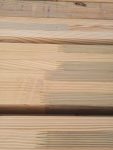 DEAR POLE BARN GURU: What are the poles shaped like? For instance 6×6 square (?cut corners like landscape or true square 6×6″)? I’m having a Drafting company draw up a gable porch (attached to house) to replace metal carport overhang. 3-Gable style 3-stall carport 26’x20′ and matchjbg 3-gable 3-stall utility boat/Rv port, center stall (gable) is raised 36’x24′. They are what I call glorified pole barns. I’m already obligated for the engineering @$4k. Porch is on 8×8 cedar posts, 6×4 beams. Carports using 6×6, 6×4 beams that Extend beyond eve w/curved end like a pergalo look (Tuscan). Metal roof. Porch will probably be planked before plywood layer, but also quoting vinyl ceiling, attaches to plywood after roof. I’m looking for builder that can handle Big beams. Told the Amish or Mennonites are best in this area – they knows the ropes. Have a Mill supplier located only 40min away, but taking bids. Nokomis, build in 2-3mo, time to get permits issued. DEBBI in NOKOMIS
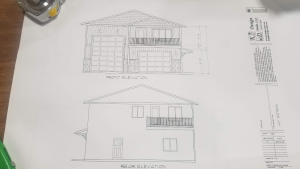
  DEAR POLE BARN GURU: I have found and customized single sloped barndominium house plan that is 96′ x 34′ (living area 49×34, garage 45×35) with a 10′ covered rear porch that extends from the roof. The plan was a generic plan i found online that calls for a 2:12 roof pitch. My question is…Would this 2:12 pitch at this width (35′) work for a home in Central MN considering the snow loads? There is a bearing wall that will run the length of living area at 15′, but not in the garage. ROBERT in SAUK RAPIDS
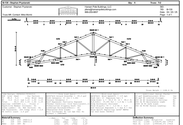
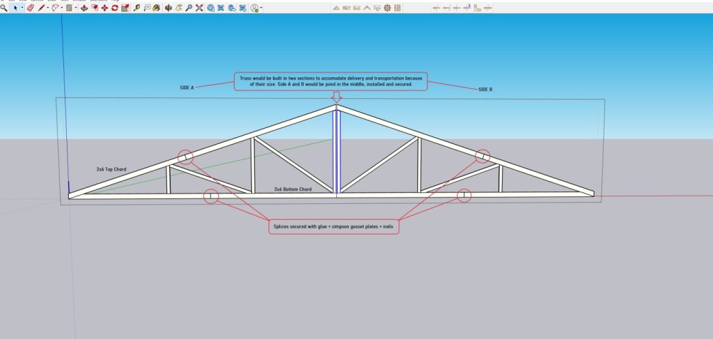
 Most often steel truss post frame kits are being sold as ‘roof only’ structures – in order to drive prices down. I have seen some great prices advertised, however as prices get lower, so does usually quality and or service. Things tend to be not included, such as trims and condensation controls. Most of these buildings are not engineered, other than maybe trusses. However, even your best steel truss engineering is negated if quality controls are not present at wherever they are being manufactured. Use of steel of a lesser grade or thickness than specified can compromise strength. Pre-manufactured trusses are supposed to have in plant quality control and random quarterly third-party inspections, having spoken with a few of these (in hopes to find a reliable provider of steel trusses) – none of them appear to be aware of this requirement. Steel trusses should also be fabricated by certified welders. While I am sure there are some great steel truss providers, they are seemingly difficult to find.
 My recommendation would be to use wood trusses. If you are trying to gain interior clear height, wood trusses can closely mimic what steel will do. Wood trusses are far easier to finish overhangs and if you want to have a ceiling finished at bottom chord height, wood trusses make it very easy to achieve. Wood trusses are subject to extremely stringent quality control standards. Every set of trusses we manufacture has to have extensive records kept to verify accuracy of members and connectors, plus – we have third party inspections.

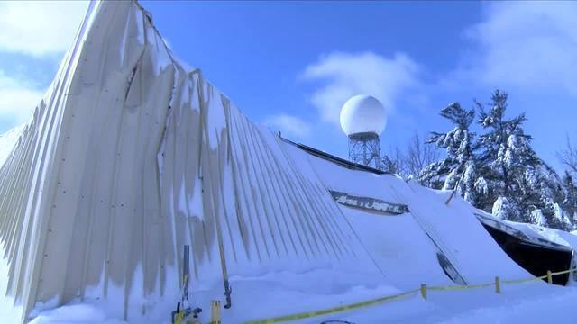
 DEAR RYAN: My gut and your gut are in agreement here. Unless this kit came complete with steel trusses as part of a system designed to support your 40 pounds-per-square foot snow load I think your buddy has a white elephant on his hands. Our clients wanting round pens would typically erect a 60 foot square post frame building and use panels to create an interior ’round’ space. This assures them of an engineered structure capable of handling appropriately snow and wind loads. There might be a solution to what your buddy has, but it is not going to come cheap and should start with hiring a Registered Professional Engineer.
 DEAR POLE BARN GURU: Do these withstand the hot weather in Las Vegas NV. Have you sold one in this area or know of a contractor that you have worked with if so. PAUL in LAS VEGAS
 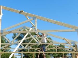 This morning Hansen Pole Buildings’ Designer Dennis asked a question of me which I had failed to address in the past 1000 plus blog posts, “I was looking on blogs couldn’t find difference between roof trusses designed for ceiling load and not designed”.
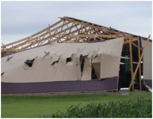
 I spent two decades in management or owning prefabricated metal connector plated wood truss plants. In my humble opinion – attempting to fabricate your own trusses of this magnitude is a foolhardy endeavor, for a plethora of reasons:
 DEAR MARK: Your roof purlins appear to be adequate to support this type of a snow load. As to trusses, I would reach out to Morton Buildings with your site address and they should be able to pull up truss drawings for your building. If not, you would need to retain services of a Registered Professional Engineer who could do an actual inspection of your trusses and run calculations to determine exactly their capacity.
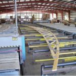 DEAR ANDREW: Can and should are not often same.
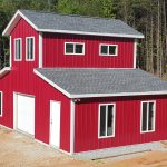 DEAR DAVE: Unless your window’s vinyl frame was actually damaged, in most instances a glass company can do a repair of just broken glazed portions. I would suggest a call to Capital Glass in Reno (775)324-6688 as this appears to be in their wheelhouse and they service Fernley.
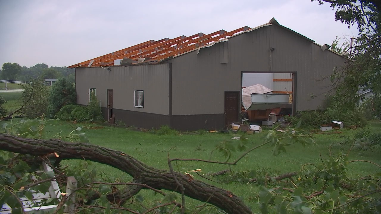
 We typically would use 2×6 #2 on edge for these recessed (between truss pairs) roof purlins. Here are the calculations:
 As we see in Chapter 1 of the Post Frame Building Design Manual (PFBDM), post frame construction has been around for hundreds of years. The performance, life expectancy, and reduction of material and labor costs are all reasons that this type of construction is becoming more popular today. We see not only construction in agricultural settings, but residential construction is rapidly growing in today’s price and time conscious market. However, structural design is critical to ensure long life and adequate performance of the building.
 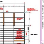 This is just one of many reasons why post frame buildings should be designed by a Registered Professional Engineer.
 Well John, you have left out a crucial part. One no proper pole barn should be without. Plans designed and sealed by a Registered Professional Engineer specific to your building at your site. To build without them is, in my humble opinion, fool hardy and I cannot endorse your plan of attack or methods of construction without them. Outside of this – attempting to field construct your own roof trusses is not a good choice. Prefabricated trusses are truly a bargain, especially when considering risks involved should your home made trusses collapse injuring or worse killing you or a loved one.
 Face it, we humans are dimensionally challenged. Even though we have an idea a basketball hoop will be at 10 feet, we think our car needs a door this height. We want to make certain you design a building with adequate spaces for your activities. This includes properly sized doors, properly spaced, to actually allow prized possessions in or out without damage to your building or something treasured.
 Risk Category I buildings are based upon a once in 25 year probability of minimum design loads being exceeded. Risk Category II once in 50 years, while Categories III and IV are once in 100 years.
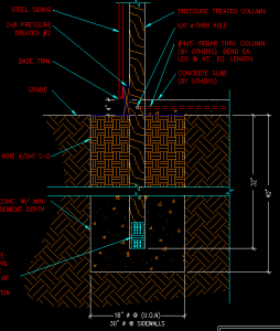 I was speaking to Rachel and she gave me your email to see if you might be able to answer a question for me. I hired complete a 50’x 80’ x 12’ pole barn here in Huntley, MT. The company showed up on the job yesterday and drilled the holes and started setting posts. Posts are 8’ center. They set the corner posts and maybe 6 sidewall posts and 4 endwall posts. The other posts were placed in the drilled holes and left for completion today/tomorrow. When I inspected the posts that were placed but not set (no backfill) I noticed that there was no footing or no cleats attached to post base to prevent uplift. When I questioned the owner of the company what he was using for footings he stated nothing added just solid tamped. I immediately called him and questioned his reasoning and got the I have been building these like this for 25 years. My question is on average what is the post load in psi on the 50’ x 80’ x 12’ pole barn with a 40# snow load? My soil has a bearing capacity of 2100 psi.”

 Until I read their next paragraph: