Tight-grained Wood is More Resistant to Premature Decay
When Hansen Pole Buildings changed our business model in early 2024 to provide lumber from our wholesale distribution center, rather than outsourcing, it caused some unanticipated side benefits.
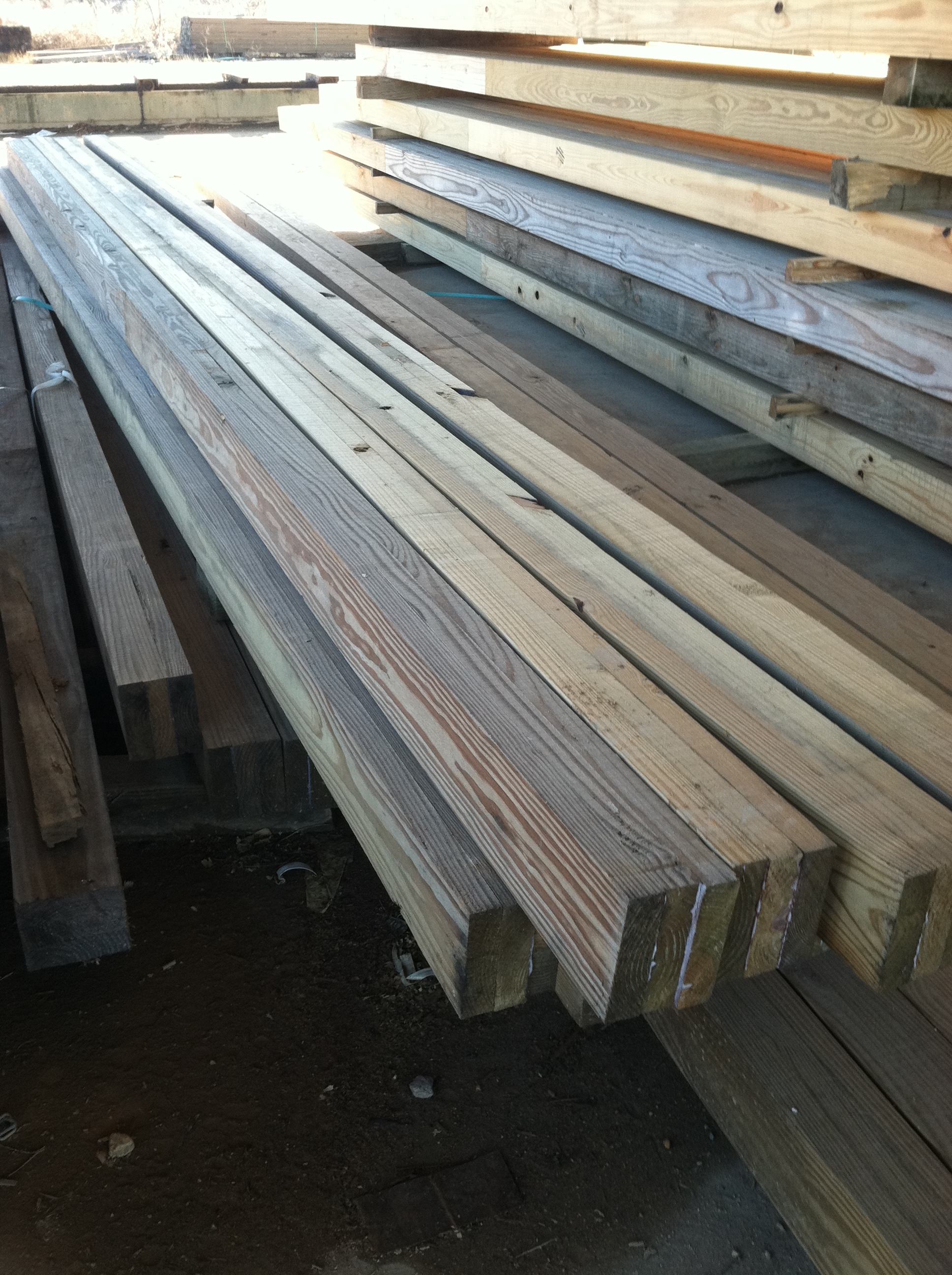
Amongst our decisions was what to do about wind resisting, roof supporting columns. Previously, we had been at a mercy of availability. While, in our ideal dream world, we would always have used glulaminated columns, they are just not readily available in most of our country.
 We opted to special order our columns – having them manufactured only from high strength 2400f msr lumber. (For some extended reading on msr lumber, please see https://www.hansenpolebuildings.com/2024/04/msr-lumber-producers-council-today/). Typically, glulaminated columns for post-frame buildings are a product of (at best) #1 grade Southern Yellow Pine (SYP) for pressure preservative treated lower portions and 1650f msr for untreated uppers. In 2×6, #1 SYP has a fiberstress in bending of only 1350f!
This makes Hansen Pole Buildings’ columns over 77% stronger in bending than lower portions of competing columns!
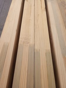
2400f msr lumber’s strength comes, in part, to it being tighter-grained. Tight-grained is generally more resistant to premature decay than wood with a wider grain, Key reason for this is tight-grained wood is denser and less permeable to moisture. This makes it harder for moisture to penetrate, reducing decay risks.
Decay-causing fungi require a consistent moisture content of 20% of higher to thrive. Denser tight-grained woods have a more compact cellular structure with fewer and smaller spaces for water to penetrate and accumulate. This keeps wood below moisture threshold needed for rot to begin.
Compact structure of tight grains offers less surface area for decay-causing organisms to establish themselves. These tightly packed wood fibers and rings act as a more effective physical barrier against fungal hyphae and insects. This makes it harder for organisms to enter wood and begin breaking down its cellulose and lignin. Many tight-grained woods contain natural oils and resins providing additional protection against fungi and insects.
Wood with a straighter, tighter grain is more dimensionally stable and less prone to warping, twisting and cracking. These cracks and separations can create entry points for moisture and fungi, accelerating decay processes.
Aren’t these high strength Glulaminated columns going to be extremely expensive?
In a word – NO!
We order hundreds of thousands of board feet of these columns every year, with this volume allowing us to keep our costs (and price to our clients) low.
Your building deserves to be both strong and durable. For “The Ultimate Post-Frame Building Experience” call Hansen Pole Buildings today 1.866.200.9657.
 Most often steel truss post frame kits are being sold as ‘roof only’ structures – in order to drive prices down. I have seen some great prices advertised, however as prices get lower, so does usually quality and or service. Things tend to be not included, such as trims and condensation controls. Most of these buildings are not engineered, other than maybe trusses. However, even your best steel truss engineering is negated if quality controls are not present at wherever they are being manufactured. Use of steel of a lesser grade or thickness than specified can compromise strength. Pre-manufactured trusses are supposed to have in plant quality control and random quarterly third-party inspections, having spoken with a few of these (in hopes to find a reliable provider of steel trusses) – none of them appear to be aware of this requirement. Steel trusses should also be fabricated by certified welders. While I am sure there are some great steel truss providers, they are seemingly difficult to find.
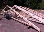 My recommendation would be to use wood trusses. If you are trying to gain interior clear height, wood trusses can closely mimic what steel will do. Wood trusses are far easier to finish overhangs and if you want to have a ceiling finished at bottom chord height, wood trusses make it very easy to achieve. Wood trusses are subject to extremely stringent quality control standards. Every set of trusses we manufacture has to have extensive records kept to verify accuracy of members and connectors, plus – we have third party inspections.
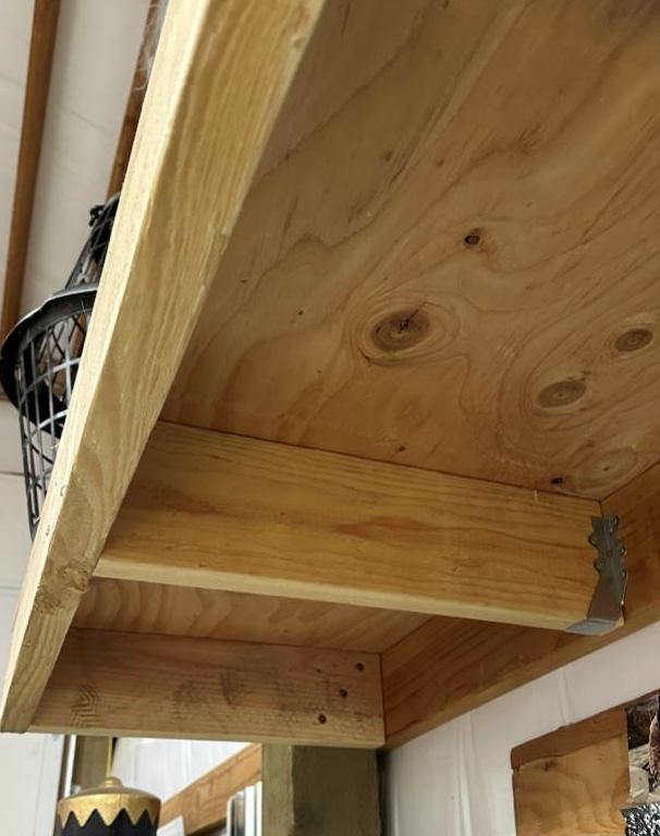
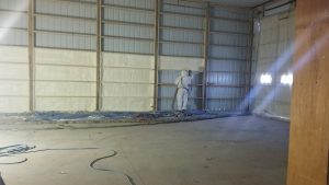 DEAR RON: Only articles I have read in regards to possible premature steel degradation have been on websites selling other types of insulation, so I take them with a block of salt. I have closed cell spray foam in my own post frame barndominium and we used it when we added onto our warehouse, can’t say we have experienced any negative challenges. We have also had hundreds of clients successfully use closed cell spray foam applied directly to steel roofing and siding.
 Basic Stats for Post-Frame
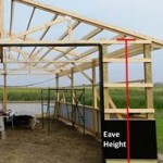 EAVE HEIGHT
 APPROPRIATELY SIZE SPACES
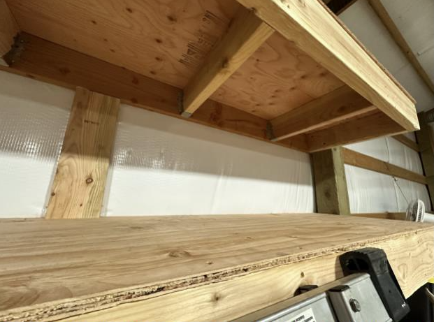
 My first choice would be to design your building to be capable of supporting a ceiling, use raised heel trusses and blow in fiberglass insulation. With raised heel trusses you can get full thickness from wall-to-wall and you do not end up heating dead space between roof trusses. Roof steel should be ordered with a Integral Condensation Control (
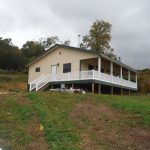 Most crawl spaces are created with dirt floors, face it, they are low budget and meet Code with a 6mil black Visqueen Vapor Barrier installed. Now retired Hansen Pole Buildings’ Designer Rick Carr built himself a hunting cabin over a crawl space a year ago and decided to take a slightly different route. He opted to do a thin layer of concrete to cover ground in his crawl space, with an idea of being able to roll around using a mechanic’s creeper, should he need to work on sub-floor utilities. Here is an excerpt from part of Rick’s planning:
  DEAR SHANE:
  Sturdi-Wall Plus brackets are used in a wet set concrete application and provide highest strength bracket to foundation connection when concrete is fully cured. SWP brackets require less concrete coverage than Sturdi-Wall brackets, allowing them to work well in pier foundations, post repair, and renovations. #4 rebar is used in all Sturdi-Wall Plus brackets, except SWP 8 Series where #5 rebar is used. Sturdi-Wall Plus brackets are available in Standard, OT and GL models.
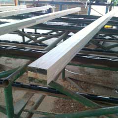 “Justine, pardon me for being confused but: If the tops of glulam posts were manufactured that way to allow cutting, why are they not all that way? There is no rhyme or reason to them. Some of them are laminated all the way to the end and some of them are not. Some of them have one board not laminated in the 3 ply and some have no lamination between the any of the boards on the end.
 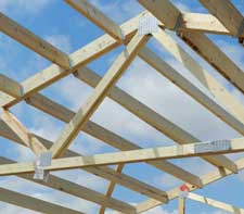 As pole buildings have gravitated from the farms of the 1950’s into the mainstream of popular construction, their owners have been looking for more appeal than what was offered by the average tractor shed.