NEW Hansen Pole Buildings Roof Purlins and Connections
Hansen Pole Buildings has always utilized what is known as recessed roof purlins, where purlins are placed between roof truss top chords.
Top of roof purlins and top of trusses are at same height and purlins were connected with typical standard joist hangers. This resulted in clients (or their building erectors) having to carefully place joist hangers to keep purlins from being too high, or too low in relationship to their respective trusses. Adding to this complexity, joist hangers were to be attached to double trusses with 10d common nails (.148” diameter x 3” long).
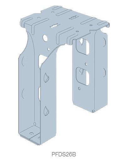
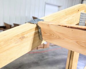
We wanted to make this into an easy connection, so now are providing a Simpson Strong-Tie PFDS26B (for 2×6 roof purlins) or PFDS28B (for 2×8 roof purlins). This part easily slides into place over a pair of trusses, automatically establishing proper purlin height. It fastens to truss pairs with SD9212 screws – three each side for 2×6, four each side for 2×8. These screws also are used to pair truss top chords, where previously two or three 10d common nails were required, usually roughly every eight or nine inches. SDWS9212 screws are also used to attach hangers to purlins, rather than 10d x 1-1/2” joist hanger nails.
Roof purlins were previously evenly spaced, resulting in some challenging measurements. We now have standardized spacing to fall so measures are evenly divisible into eight (8) feet. Examples are 32”, 24”, 19.2”, 16” all of which are keyed to markings on tape measures.
By again utilizing high strength msr lumber for roof purlins, spans previously needing to be 2×8, or in some cases even 2×10, can be done with 2×6 lumber.
We have even made it easy to quickly identify lumber to be used as roof purlins – one end will arrive spray painted PURPLE for ‘field’ purlins and PINK for purlins in high load areas – such as drifting near ridge in snow country. If you (or your erector) need to trim a board, please trim unpainted end, as this makes it easy for you (if you hired a builder) or an inspector, to quickly identify wood as being properly utilized!
We have improved speed and accuracy of installation, reduced dead weight of roof system and increased system strength and reliability!
BUT WAIT, THERE’S MORE
I mentioned how double truss top chords are usually nailed together with lots of nails. Well, we are now connecting truss webs and bottom chords with Simpson SDWS16300 structural screws – spaced much further apart than nails were. Fewer and stronger fasteners!
Call 1.866.200.9657 TODAY to participate in “The Ultimate Post-Frame Building Experience”.
And, don’t forget to watch for our next article!
 I don’t often get to answer questions posed from outside North America. I toured England and Scotland for 23 days in 1997, however sadly did not get south of London. Not knowing what species of lumber you are using, calculations below are based upon weakest of common North American framing lumber – Southern Yellow Pine (SYP) with a Fb (fiberstress in bending) value of 1000 psi (pounds per square inch), equal to 6.89 N/mm2. This would fall between your common designations of C16 (5.3 N/mm2) and C24 (7.5 N/mm2). The following describes 2×6 SYP #2 purlins spanning a 10.8′ bay, with an on-center spacing of 39″ (sf).
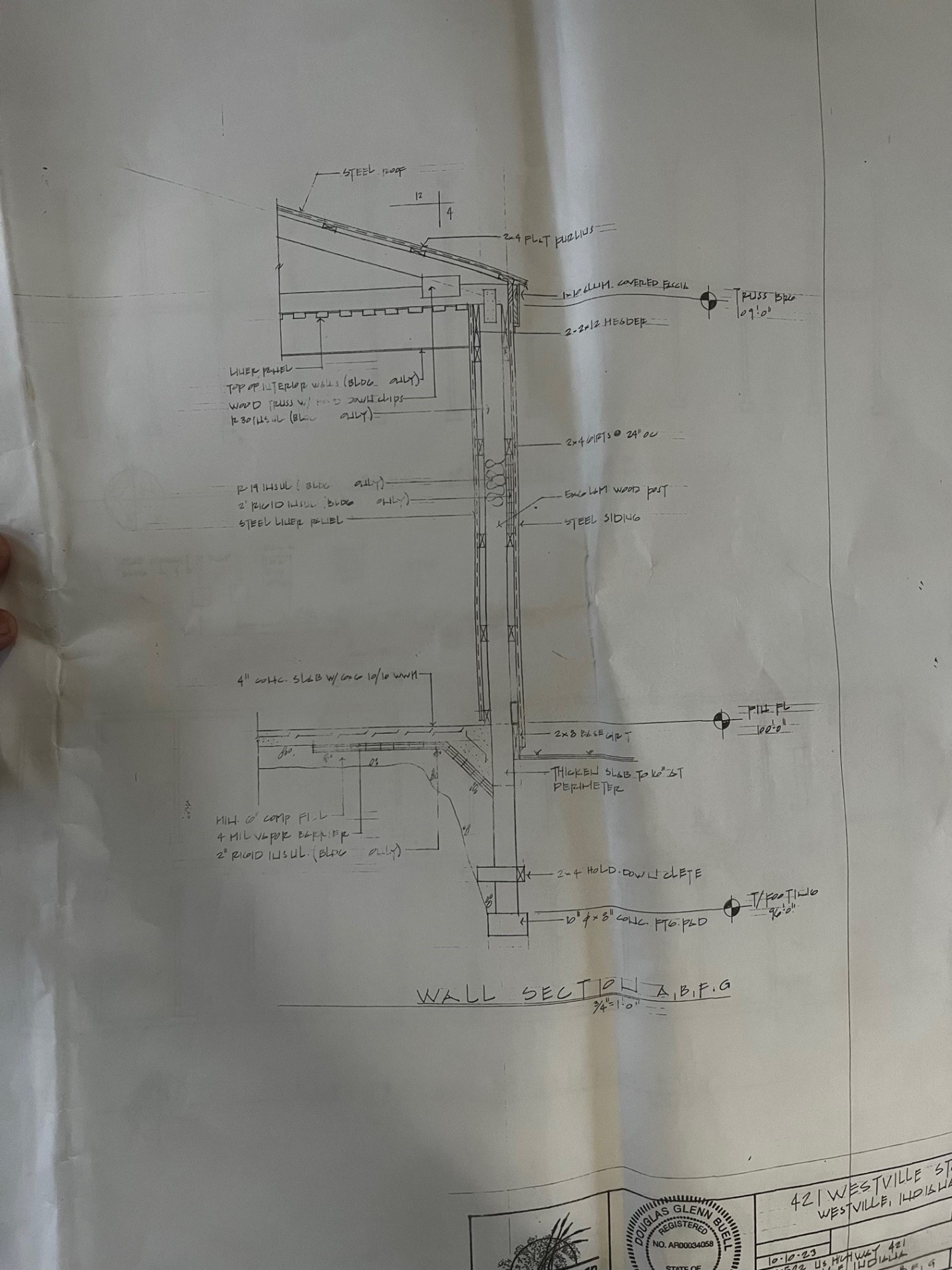
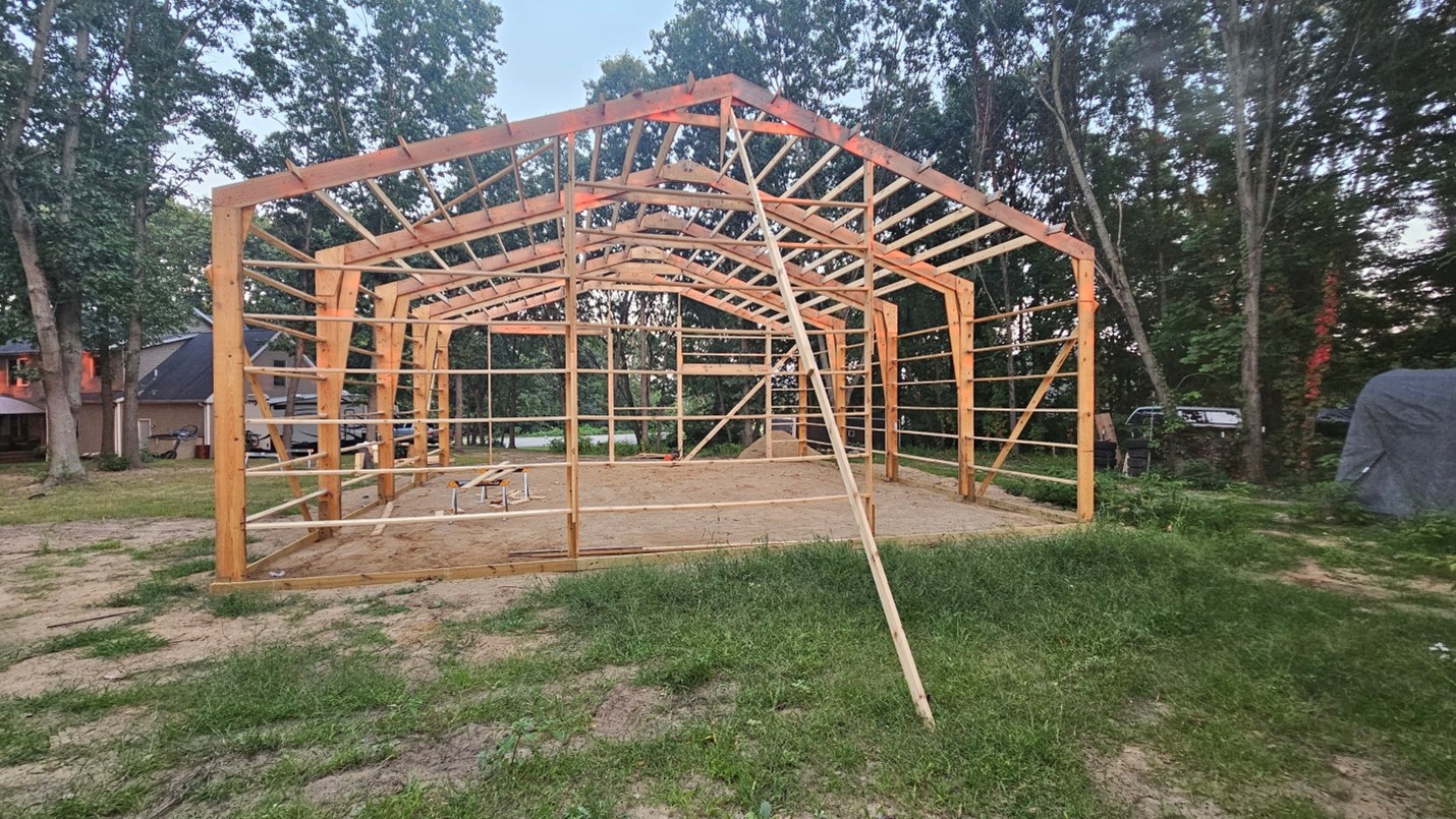
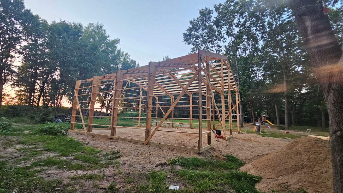
 DEAR MARK: Your roof purlins appear to be adequate to support this type of a snow load. As to trusses, I would reach out to Morton Buildings with your site address and they should be able to pull up truss drawings for your building. If not, you would need to retain services of a Registered Professional Engineer who could do an actual inspection of your trusses and run calculations to determine exactly their capacity.
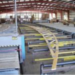 DEAR ANDREW: Can and should are not often same.
 DEAR DAVE: Unless your window’s vinyl frame was actually damaged, in most instances a glass company can do a repair of just broken glazed portions. I would suggest a call to Capital Glass in Reno (775)324-6688 as this appears to be in their wheelhouse and they service Fernley.
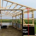 EAVE HEIGHT
 APPROPRIATELY SIZE SPACES
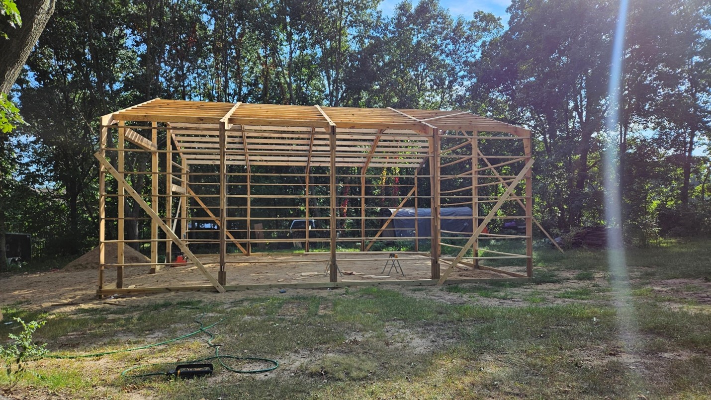
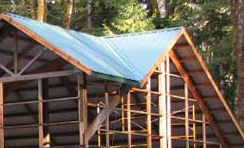 Main roof is framed up, including purlins across area where reverse gable will intersect. 2×12 blocking is then placed between main roof purlins, centered on what will eventually be the middle of the valley. This provides a landing point for intersecting roof purlins from reverse gable (next to be installed). Once these purlins are in place, any reflective radiant barrier (RRB) is installed (I prefer using roof steel with Integral Condensation Control to a RRB). Valley flashing is then installed. We furnish Emseal® self-expanding foam closures to seal between valley flashing and roof steel, following slope of valley flashing. Roof steel is then applied and you are buttoned up tight.
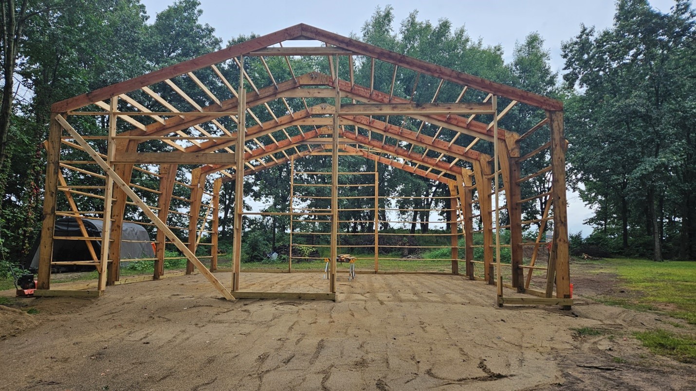
 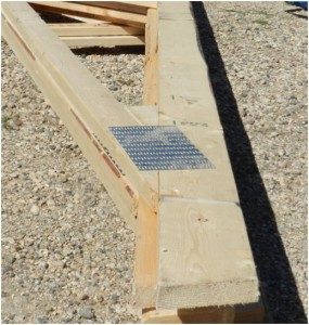 Building plans are drafted prior to receipt of truss drawings, so trusses as drawn on your plans are merely a depiction of what they may look like. Top and bottom chords as well as internal diagonal webs may be entirely different. The roof slopes will be accurate. Your building’s roof purlins certainly may hang below roof truss top chords, as this has no bearing upon your ability to insulate (please refer to Figure 9-5 of your Hansen Pole Buildings’ Construction Manual). As your roof has a Reflective Radiant Barrier, if you intend to use batt insulation between purlins, make sure to use unfaced insulation without a vapor barrier on underside, otherwise moisture can become trapped between two vapor barriers. This can lead to ineffective damp insulation as well as potential mold and mildew issues.
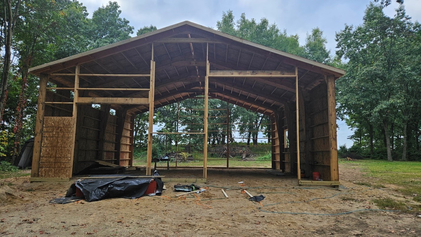
 We look for trends in questions asked by owners of existing pole barns – usually not even those we provided! There are a couple of these our team has decided to address and we have so far done a very poor job of letting our clients know we have done so.
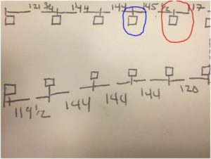
 Our client has ordered a pole building kit package which is designed around sidewall columns spaced every 14’. For those who care, the building has a design roof snow load of 30 psf (pounds per square foot) and the actual roof dead load carried by the roof purlins (including the purlins themselves) is 1.626 psf. Our engineer designs a roof system with a pair of trusses at each sidewall column, and 2×8 #2 roof purlins joist hung between the trusses and placed 24 inches on center. The engineer prints off two sets of plans and supporting calculations, places his seal and signature on them, and sends them off to our client.


