Tag Archives: Simpson brackets

4×4 or Double 2×4 Bay Roof Purlins?

4×4 or Double 2×4 for 12’ Bay Roof Purlins?

Reader JOHN in HUNTSVILLE writes:

“If you have trusses spaced at 12 feet, can a 4x4x12 or two 2x4x12’s span the distance given the minimal snow loads in Arkansas? I know this is question #2 but what kind of joist hangers do you use (Simpson Number or equivalent) for purlin attachment to trusses?”

We typically would use 2×6 #2 on edge for these recessed (between truss pairs) roof purlins. Here are the calculations:

Assumptions:

Roof slope = 4:12 (18.435° roof angle)
Trusses spaced 12-ft. o.c.
Purlin span = 11.75-ft.
Purlin spacing = 24 in.
Purlin size 2″ x 6″ #2
Roof steel dead load = 0.63 psf steel American Building Components catalogue
Roof lumber dead load = 62.4 pcf * 0.55 lbs/ft.3 / (1 + 0.55 lbs/ft.3 * 0.009 * 0.19) * (1 + 0.0019) * 1.5″ / 12 in./ft. * 5.5″ / 12 in./ft. * (12′ – 3″ / 12 in./ft.) / 12′ / (24″ / 12 in./ft.) psf in purlin weight based on 0.55 G NDS = 0.963 psf
Total purlin dead load = 1.593 psf
Check for gravity loads

Bending Stresses

Fb: allowable bending pressure
Fb‘ = Fb * CD * CM * Ct * CL * CF * Cfu * Ci * Cr
CD: load duration factor
CD = 1.25 NDS 2.3.2
CM: wet service factor
CM = 1 because purlins are protected from moisture by roof
Ct: temperature factor
Ct = 1 NDS 2.3.3
CL: beam stability factor
CL = 1 NDS 4.4.1
CF: size factor
CF = 1 (not applicable to SYP)
Cfu: flat use factor
Cfu = 1 NDS Supplement table 4A
Ci: incising factor
Ci = 1 NDS 4.3.8
Cr: repetitive member factor
Cr = 1.15 NDS 4.3.9
Fb =1000 psi NDS Supplement Table 4-A
Fb‘ = 1000 psi * 1.25 * 1 * 1 * 1 * 1 * 1 * 1 * 1.15
Fb‘ = 1437.5 psi

fb: bending stress from roof live/dead loads
fb = (purlin_dead_load + Lr) * spacing / 12 * cos(θ) / 12 * (sf * 12 – 3)2 / 8 * 6 / b / d2 * cos(θ)
Lr = 20 psf using the appropriate load calculated above
fb = 21.593 psf * 24″ / 12 in./ft. * cos(18.435) / 12 in./ft. * (12′ * 12 in./ft. – 3″)2 / 8 * 6 / 1.5″ / 5.5″2 * cos(18.435)
fb = 1060 psi ≤ 1437.5 psi; stressed to 73.7 %

Deflection

Δallow: allowable deflection
Δallow = l / 180 IBC table 1604.3
l = 141″
Δallow = 141″ / 180
Δallow = 0.783″
Δmax: maximum deflection
Δmax = 5 * Lr * spacing * cos(θ * π / 180) * (sf * 12 – 3)4 / 384 / E / I from http://www.awc.org/pdf/DA6-BeamFormulas.pdf p.4
E: Modulus of Elasticity
E = 1400000 psi NDS Supplement
I: moment of inertia
I = b * d3 / 12
I = 1.5″ * 5.5″3 / 12
I = 20.796875 in.4
Δmax = 5 * 20 psf / 144 psi/psf * 24″ * cos(18.435° * 3.14159 / 180) * (12′ * 12 in./ft. – 3″)4 / 384 / 1400000 psi / 20.796875 in.4
Δmax = 0.559″ ≤ 0.783″

2×4 #2 and 4×4 #2 Southern Pine have Fb values of 1100

Sm (Section Modulus) of a 2×6 is 7.5625; (2) 2×4 nailed together would be 1.5″ width x 3.5″ depth^2 x 2 members = 6.125 I would = 10.71875; 4×4 would be 7.146 with I = 12.5052

The (2) 2×4 would be stressed to 82.7% in bending however Δmax = 1.085″ so would fail due to being over deflection limits

How about a 4×4? 70.9% in bending Δmax = 0.9296″ so would also fail due to being over deflection limits

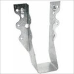
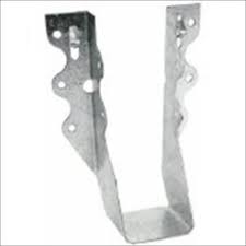
For our 2×6 purlins, we specify a Simpson LU26

Commercial Post Frame Building Blunder

Commercial Post Frame Building Blunder

My Facebook friend Dan recently commented upon this article https://www.hansenpolebuildings.com/2020/03/there-is-a-right-way-and-this-way/ wanting to know if I could show some other building blunders.

Yes Dan, I can.

As Technical Director for Hansen Pole Buildings since 2002, I have gotten to assist a few DIYers and post frame builders with their building questions. DIYers are generally fabulous, and their stories usually begin with something similar to this:

“I have made a mistake worse than anything you possibly ever seen, can you help me?”

To them my response is most usually, “As a post frame building contractor, I ran as many as 35 crews in six states. If something could be done wrong, they probably did it, so how can I assist you?”

Most builders usually take a different tack, “Your plans are stupid and your engineer is an idiot!”

And from me, “Now we have this settled, describe your challenge and we can work towards a solution.”

Please keep in mind, our third-party engineer sealed blueprints are similar whether for a builder or someone doing DIY. We are not picking specifically upon builders by giving them less to work from.

In this particular instance, an allegedly professional builder has found a way to go above and beyond any bad I have ever previously experienced.

Far beyond.

This article’s photo shows a 60 foot span prefabricated roof truss, somehow hanging in air two feet past a building endwall. Builder contacted us because he was “short” on trim. From this picture, I am guessing trim is not all he is short on.

This truss was supposed to be notched into the corner and endwall columns by 1-1/2 inches, so it has full bearing at each point. Horizontal 2×4 framing (shown as being cut to fit between end truss webs) was to have been placed upon the end truss face to attach steel siding. Roof purlins, on edge, were to go across top of this truss to support a two foot overhang. Engineered Simpson brackets were provided to attach purlins to truss and solid blocking was to be placed between overhanging purlins above the truss.

I am totally baffled as to what is supporting this truss, or how the builder believed this was going to be correct. Certainly he did not look at building plans or open our Construction Manual. This is one of several  pretty much unbelievable FUBARs on this building – and it resulted in my making a recommendation to dig a deep trench at one end of the building and bulldoze everything into it!

Dear Pole Barn Guru: Toe Nail Purlins or use Hangers?

Welcome to Ask the Pole Barn Guru – where you can ask questions about building topics, with answers posted on Mondays.  With many questions to answer, please be patient to watch for yours to come up on a future Monday or Saturday segment.  If you want a quick answer, please be sure to answer with a “reply-able” email address.

Email all questions to: PoleBarnGuru@HansenPoleBuildings.com

DEAR POLE BARN GURU:It looks like your double truss system uses hangers between the trusses rather than the boards running on top of the trusses.

When I see these used on decks it sometimes looks like the nails that are toe-nailed into the connectors don’t do anything as they are at the very end of the board. The board splits or chips out.

Have I just seen it done improperly or perhaps I’ve seen the wrong types of hangers or nails being used?

I’m guessing you’ve seen your fair share of improperly installed connectors so I’m looking forward to what you have to say.

Thanks NOVICE IN MILTON

DEAR NOVICE: The Hansen Pole Buildings double truss system (as well as the special requests we get for widely spaced single trusses) do utilize engineered steel connectors to attach the roof purlins to the sides of the trusses.

As an experiment, I looked today at the hundreds of hangers we have installed on a 42’ x 120’ self storage building being constructed for Eric (one of the Hansen Pole Buildings owners). All of the hangers for the project are manufactured by Simpson Strong-Tie:

https://www.hansenpolebuildings.com/blog/2013/08/simpson/

The hangers installed are their LU26, LU28 and H1 brackets.

The roof purlins being nailed into are kiln dried 2×6 and 2×8 of Douglas Fir (DFir) and SPF (Canadian Spruce-Pine-Fir). All of the nails used in the hangers are joist hanger nails (#10 x 1-1/2” long) which are designed specifically for use in engineered metal connectors.

https://www.hansenpolebuildings.com/blog/2013/01/tico-10d-common-nails/

I was unable to find a single case on Eric’s large building with hundreds of joist hangers where the nails contributed to an end split in a purlin or a portion of the roof purlin being split away.

I do have some theories as to what may be the cause of what you have seen on decks.

Theory #1 – other than a few specially designed brackets, joist hangers are designed for the nails to be installed at right angles to the wood. Toe-nailing (driving the nails in at an angle) could be responsible for splits.

Theory #2 – in your part of the country, the vast majority of lumber used for decks is pressure preservative treated Southern Yellow Pine (SYP). It could very well be the SYP lumber is more susceptible to splitting than the species of wood provided for use in the building we are currently constructing.

Simpson Strong-Tie produces millions upon millions of engineered steel connectors every year – if there existing an inordinate (or any) number of failures due to the use of their products, they would be on top of making changes in the design to prevent them.

Me – if my choice is to nail a purlin over the top of the truss (which in the great majority of cases does not calculate out to be adequate structurally) or to use an engineered connector – the connector is going to win every single time.

DEAR POLE BARN GURU: I am currently assembling a Hansen Pole Building kit package. The building has a transition in roof slope from a steeper slope in the enclosed area, to a flatter slope in the open attached side shed.

In following the instructions in your Construction Guide, I note the solid wall between the enclosed and open portions is to have the wall framed and wall steel installed prior to placement of the roof steel.

My questions are these – I’m running the J trim at the top eave girt between the enclosed wall and shed.  Do I need to flow around the shed rafters with the J trim? Will I be able to square the roof if I put the wall steel on? STUMPED

DEAR STUMPED: Yes – the J Trim goes around the rafters which project through the wall. And as long as this wall is plumb before installing the wall steel, it will not interfere with being able to square up the roof.

Simpson Strong Tie

I believe in the use of engineered connectors, wherever they can be prudently used in post frame (pole building construction). The average consumer who has visited a lumber yard, or a big-box home improvement center has probably seen many of them, but may not have given them more than a passing thought.

About two decades ago, when I was constructing pole buildings, one of our clients called us after a freakishly high wind storm (significantly higher than the design Code required wind load, at the timSimpson Strongtie H1 Hanger
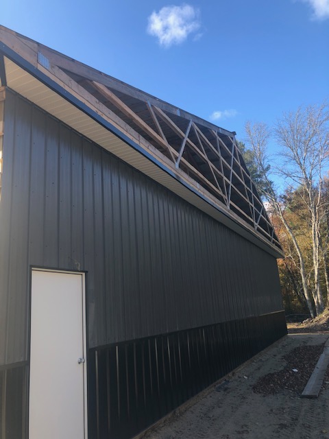
e, of 70 miles per hour) had plowed through their building. This particular building had 2×6 roof purlins on edge, cantilevered over the endwall roof truss, to support the end overhang. The wind literally tore the purlins off the end truss, and flipped the first bay of the roof upside down onto the second bay!

In doing forensic analysis, after the wind died down of course, we determined the connection of the purlins to the end truss with toenails was adequate to have withstood a Code wind load, but not the wind speeds which had attacked the building. The solution for the repair, as well as for future building designs was to utilize a Simpson H-1 bracket to attach overhanging roof purlins to end trusses.

Typical Hansen Pole Buildings utilize many engineered steel connectors manufactured by Simpson.  Most typically they include joist hangers to attach roof purlins and bottom chord bracing to interior trusses and strap hangers to attach X bracing to trusses as well as end trusses to columns in high wind load applications.

There is an interesting history to the development of Simpson brackets, which I had been unaware of:

“The Simpson Family has been in the San Francisco Bay Area building community since 1914, but it wasn’t until the mid-1950s that they launched the business that would become a world leader in their industry. And it all really began with a visit from a neighbor.

“The doorbell rang one Sunday night in 1956,” recalled Barclay Simpson, who took over a window screen business from his father in 1947. Outside was a neighbor who was looking to make structural connectors for the ends of 2x4s for a flat roof. Could Simpson help him out? “I said, ‘Of course’ and then tried to figure out whether I could.”

It was that request for a joist hanger that led to the creation of Simpson Strong-Tie, a global company with more than $550 million in sales worldwide (2010), more than 1,800 employees, and nine U.S. and 10 international manufacturing locations. As a publicly traded company, Simpson Manufacturing Co. has had exceptional performance records since the company’s 1994 IPO. As a result, it has consistently commanded the respect of industry analysts for its market leadership, strong fiscal management, and innovative approach to growth.”

My experience is, if an engineered steel connector exists, Simpson makes it – and if it doesn’t exist, their engineering team will find a solution!