Tag Archives: engineer

Can I Draw Up My Own Building Plans and Have an Engineer Stamp Them?

Can I Draw Up My Own Building Plans and Have an Engineer Stamp Them?

This became a rather heated topic in a recent social media discussion. Question posed was could an individual draw their own post-frame building plans, take them to an engineer, and have the engineer stamp them.

A professional engineer’s role in signing and sealing engineering drawings, plans, and specifications is a core issue within professional engineering practice. A professional engineer’s signature and seal is a legal representation engineering drawings, plans, and specifications were prepared under professional engineer’s responsible charge (direct control and personal supervision) and certifies work was performed competently, meets professional care standards, and acceptable practice standards.

NSPE (National Society of Professional Engineers) Board of Ethical Review has addressed this issue on numerous occasions. For example, in BER Case 86-2, Engineer A was Chief Engineer within a large engineering firm and affixed his seal to some plans prepared by registered engineers working under his general direction who did not affix their seals to these plans. At times, Engineer A also sealed plans prepared by non registered, graduate engineers working under his general supervision. Because of the organization’s size and the large number of projects being designed at any one time, Engineer A found it impossible to give a detailed review or design check. Engineer A believed he was ethically and legally correct in not doing so because of his confidence in the ability of those he had hired and who were working under his general direction and supervision. By general direction and supervision, Engineer A meant he was involved in helping to establish concept, design requirements, and reviewed design elements or project status as design progressed. Engineer A was consulted about technical questions, and he provided answers and direction in these matters.

In finding it was unethical for Engineer A to seal plans not prepared by him, or he had not checked and reviewed in detail, the Board noted one of the most important parts of NSPE’s Code of Ethics is reference to “direction and control” found in Section II.2.b. The Board stated accepted definition of this provision is “guidance or supervision of action or conduct; management; a channel or direct course of thought or action.” Word “control” is generally defined as “authority to guide or manage; direction, regulation, and coordination of business activities.” The Board concluded “direction” and “control” have a meaning, when combined, would suggest an engineer would be required to perform critical tasks related to preparing drawings, plans, and specifications in order for engineer to ethically affix his seal, which Engineer A did not do.

Responsibility for Collapsed Pole Buildings

  • Question Whether County is Responsible for Collapsed Pole BuildingsEllensburg’s (Washington) Daily Record published this letter from DAVE on March 5, 2022:

“To the Editor: Anybody passing through the Nelson Siding area in the Upper County some seven miles west of Cle Elum, will notice collapsed pole buildings due to the snow we had in January.

The weight of the snow (83 pounds) in that area was well below the county building codes weight limit, and yet these buildings collapsed.

The question is, what responsibility does the county building have regarding in passing this failed construction design.

I believe the insurance companies for these people that own these buildings that were built to code to satisfy the county, should expect the county to bear some if not all of the responsibility for the reconstruction cost of these buildings.

I, Dave xxxxx, private property owner over 37 years, live just one quarter of a mile east of the first two of the four pole buildings that collapsed.”

I will begin this with your local building permit issuing authority has absolutely no liability for failures due to inadequate structural design or construction. When a building permit is issued, most jurisdictions place a stamp on approved plans to advise accordingly.

Kittitas County (where these buildings are located), happens to be (in my humble opinion) on top of my list for providing to potential building owners and builders accurate site specific minimum climactic data for design. They do, however, only require a licensed design professional (Architect or Engineer) to stamp, prepare or oversee preparation of plans and calculations for pole (post frame) buildings meeting any one of these criteria:

An eave height over 16 feet
Having habitable living space
Two stories where a second floor is over 200 square feet
In areas where ground snow load (Pg) exceeds 70 psf (pounds per square foot)

To start with, Building Department loading requirements are minimums. IBC (International Building Code) 101.3 reads as follows, “The purpose of this code is to establish the minimum requirements to provide a reasonable level of safety, health and general welfare through structural strength….”

Nowhere does it say by following these minimum requirements, your building (of any sort) will not collapse in event of a catastrophic situation. Although this previous article was written in respect to wind events, snow events are obviously problematic as well: https://hansenpolebuildings.com/2018/11/500-year-storm/

*example of collapse

Back in late 1996, when I was building, we had a portion of one of our fully engineered post frame riding arenas collapse at Thorp, Washington (just West of Ellensburg and East of Cle Elum). Building was designed to minimum Code requirement with a roof snow load of 34 psf. Our client had attempted to remove some snow from roof, and had pre-collapse photos showing roughly four feet of snow on their building’s roof! Actual snow load was more than double design requirements.

Learn how to calculate snow weight here https://hansenpolebuildings.com/calculating-loads/

A smart insurance company would hire someone like me to do a forensic evaluation of these buildings as built, in comparison to engineered plans approved for construction. I am not a gambling man, however I would put forth a wager I can find one or more deviations from these approved plans on any building. This could absolve insurance providers of any liability to pay claims.

It is possible there were some engineering deficiencies contributing to these collapses, most often I would look to truss bracing, or inadequate design of purlins in drift zones (unbalanced loading).

I would encourage readers to peruse this document for further information on preventing post frame building collapses due to climactic conditions: https://hansenpolebuildings.com/2019/04/steps-to-minimize-snow-load-failures/.

Adding a Post Frame Gable Extension

Adding a Post Frame Gable Extension

A roof line extension off a post frame gable endwall is an affordable method to cover porches, patios, or even as a carport. As opposed to attaching a single sloping (shed style) roof, it will not reduce headroom or block line-of-sight. It is also easier to build as it will not entail detailed flashings to prevent water infiltration at existing building wall.

Reader MATT in AUSTIN writes:

“In 2020 we had a pole barn built (36’G x 46’L). 5′ truss spacing and posts are set about every 12′ plus door sides, etc. On one gable end we knew we wanted a deck but figured we would handle it later ourselves. But now we are thinking about the deck cover being a gable extension. Looking at doing a 10′ gable extension over a 10′ deck. We can get an auger out to set posts, but getting trusses delivered and stood up might be tough. So can we just stick build the extension and tie it back to the building? I assume that would look like setting our new posts, building a copy of the end truss on our new end, then ridge and rafters? Given the deck will need a railing anyway, I am fine doing more posts than corner posts, including center post, though it would look better with 6×6 corners and 4×4 every 8-12′ (to support end truss and railing). I am totally open to hiring you to answer questions/do design if needed. I am sure we didn’t have an engineered design for our building (not site specific at least). We are built with BMC trusses that were project specific.”


Mike the Pole Barn Guru writes:

Thank you for your kind offer of hiring me however I am not a Texas Registered Professional Engineer or Architect, so I can only guide you in a general direction. Ultimately you should be able to take my recommendations to a Registered Professional who should be able to wrap this up with a nice, tidy bow.

Across your new deck end, you can place columns at corners and every 12 feet, tall enough to reach the roofline. A 4×4 will not be adequate to resist imposed loads, 6×6 may be (make sure whatever you do use is UC-4B treated for structural in ground use). Columns must be set on concrete footings at least six inches thick and provision must be made to prevent uplift.

As your existing structure has full length columns (to top of end truss), you can sandwich a rafter to face the existing truss, with tops of truss and rafter even. In all likelihood, this will be a 2×12 #2. Place a similar rafter on the outside face of new end columns, appropriately nailing (10d galvanized commons or even better Simpson SDS screws).

Dimensional lumber or plywood furring strips can be placed between high ribs of endwall steel, allowing for rafter to be attached without having to cut existing endwall panels. SDS screws will need to be appropriately longer to accomplish a sound structural attachment.

Between rafters, 2×6 #2 purlins can be placed on edge, using LU26 Simpson hangers (or equal).

Contract Scheduling and Terms

Disclaimer – this and subsequent articles on this subject are not intended to be legal advice, merely an example for discussions between you and your legal advisor.

Please keep in mind, many of these terms are applicable towards post frame building kits and would require edits for cases where a builder is providing erection services or materials and labor.

SCHEDULING: Upon completion of all required documents by Purchaser (including, but not limited to, Instant Invoice, Door locations and Jobsite Delivery Information), Purchaser’s online approval of Seller’s plans, and appropriate payment, shipment(s) will be expedited to be as soon as is practical, however no guaranteed time frame is promised. Purchaser will receive multiple deliveries over a span of a week or more. Seller has little or no control over the exact date of arrival, nor can Purchaser specify any exact date and/or time for deliveries.

Some vendors will require Purchaser or Purchaser’s adult agent to be present at time of delivery. Materials may be delivered via any combination of USPS, UPS, FedEx or freight carrier, the choice of which is strictly determined only by Seller and/or Seller’s vendors. In the event tracking information is furnished to Purchaser, the responsibility to monitor tracking is upon Purchaser.

EXCLUSIONS: Seller is not a contractor, architect or engineer in any state, and both parties agree no such representation has been made. Seller does not and cannot endorse, nor take responsibility for the performance of any contractor or laborer hired by Purchaser, even if the name was provided by Seller. Purchaser waives any and all right of claim against Seller for non-performance of any materials improperly installed by any contractor. 

Seller cannot predict nor guarantee any permit, construction or labor costs. Any and all construction labor and equipment, as well as nails 16d or smaller, staples or tacks which can be commonly driven by pneumatic powered equipment are to be provided by Purchaser or Purchaser’s agents. The need for butyl tape sealants, water seals, closures for wall steel or polycarbonate panels, caulking or any other sealants is to be determined and furnished by Purchaser. 

While great effort is made to include web bracing material Seller does not see final engineered truss drawings prior to shipment so cannot verify, in advance, all web bracing requirements. As such, any materials for web bracing required beyond what is originally shipped with building kit, shall be furnished by Purchaser. Seller also does not furnish, nor pay for, any cement, concrete, pre-mix, rebar, wire mesh or any other materials which would be used to backfill Purchaser’s building columns or to construct any concrete floor, foundation or curb.

Concrete floors and/or continuous footings and/or foundations, electrical, plumbing, HVAC, insulation, drywall, site or grading plans, non-structural interior walls or partitions, provision for flooding, firewalls, sprinklers or other fire separations, gutters and downspouts, energy/heat loss calculations, meeting requirements of any energy code, meeting requirements of The International Wildlife-Urban Interface Code, or materials not provided by Seller, as well as the design of or specifications for any concrete work (including but not limited to driveways, porches, approaches, slabs, retaining walls, footings for walls, continuous foundations or stem walls) are specifically excluded from this Agreement and provided plans and/or calculations to be provided by Seller or third party engineer(s). 

Seller’s plans include a foundation designed as an isolated, shallow foundation with embedded columns. In the event any other foundation type be desired, or required, Purchaser will need to hire an appropriate engineer, at Purchaser’s expense. Any “plot” plans, floor plans or site tests/reports/engineering, or other “special” reports requested by any agency for Purchaser’s building are to be provided by Purchaser. Stairs, lofts, decks, mezzanines, second or higher floors, if included, will have handrails provided by Purchaser, unless otherwise specified. 

Purchaser further agrees to not enter into any other agreement, either verbal or written, with any of Seller’s suppliers, manufacturers, agents, employees or subcontractors, without the express written consent of Seller.

Contracts Are Boring…Until You Go To Court

I have one goal – for people to end up with structurally sound buildings they love. Follow these guidelines and you are far more likely to love your new building.

Your work starts before you sign a contract.

ASSUME YOUR PROJECT WILL END IN COURT

ASSUME YOUR BUILDING PROVIDER/CONTRACTOR IS UNTRUTHFUL

ASSUME YOUR PROJECT WILL BE MORE EXPENSIVE

ASSUME YOUR PROJECT WILL TAKE LONGER THAN EXPECTED

Failure to accept these four statements will set you up for grave disappointment.

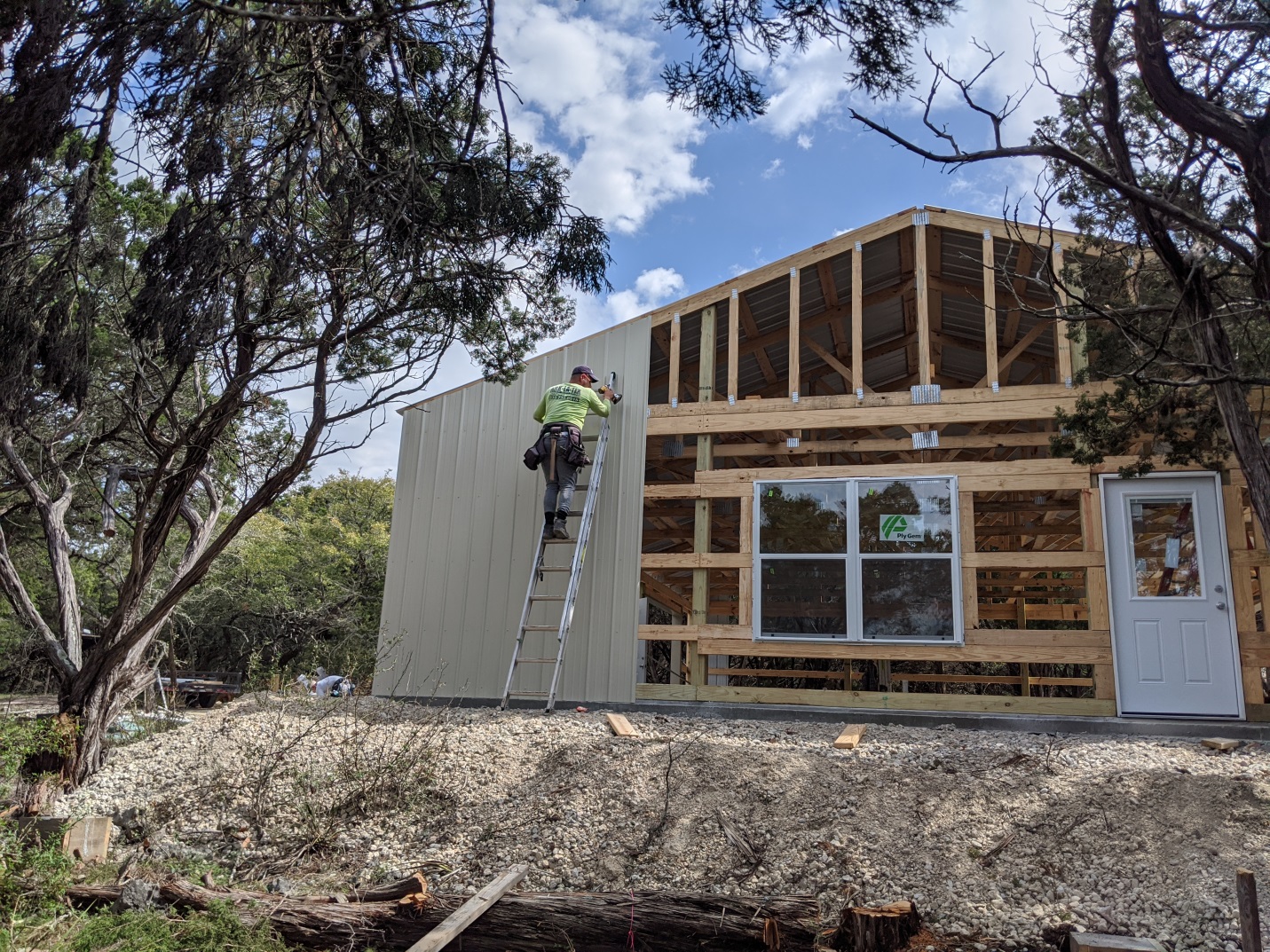
Buy Materials Yourself

Contractors generally have no qualms about using leftover materials from prior jobs, or purchasing cheaper materials than specified. If you seriously are concerned about material quality, take control yourself. Be aware, when contractors purchase materials for your building, they will mark them up. Paying for materials yourself assures you of not having liens against your property for bills your contractor did not pay.

It is very important you make decisions on exact materials you use for your building. With each type of material, there is a high end product, low end product, and something middle grade. Educate yourself on differences between each type of material, so you can choose based on your needs. If you allow a contractor to make any of these choices for you, they can really screw you over. Picking the right materials can make a huge difference.  If a contractor picks wrong materials, things are bound to go wrong.

Only Use Engineer Sealed Plans Specific to Your Building

Your building provider or contractor may have decades of experience, but unless he or she has initials “P.E.” (Professional Engineer) after his or her name, he or she is not qualified to make structural decisions. Have any deviations from plans reviewed and approved by your building’s engineer.

A building provider or contractor who sluffs off values of a fully engineered building plan does not have your best interests at heart.

Do Not Agree to a “Gentleman’s Agreement”

Always, always, always put your agreement with a building provider and/or contractor in writing. Having everything in writing has nothing to do with trust. It helps ensure everyone remembers what agreed upon terms are.  Months later you do not want to start arguing over what was originally agreed to. Contracts should be very detailed, including all expectations for both parties. 

Read the contract thoroughly, including all terms and conditions.

Keep in mind a good contract is written to provide clear communication between two parties.  It also protects both parties, and should never be “one sided”.  From my years as a general contractor, a well thought and spelled out contract (in writing) made for smoothest projects. 

Before agreeing to any work (as well as making any payment), require a written proposal describing in plain language what materials will be provided and/or work will be done. Do not sign a contract you do not fully understand. If anything makes little or no sense, ask for a written explanation. Still feel dazed and confused, or not getting what you feel are straight answers? Pay a one-time fee so a lawyer can walk you through what, exactly, it says and alert you to vague language. Terms such as “Industry Standard” have no real definition.

A total price should be as inclusive as possible. Any unforeseeable work or unit prices should be clearly addressed (like what happens if holes are difficult to dig). Maintain all paperwork, plans and permits when the job is done, for future reference.

Familiarize yourself with contract terms.

Proposals and contracts should contain specific terms and conditions. As with any contract, such terms spell out obligations of both parties, and should be read carefully. Be wary of extremely short or vaguely worded contracts. A well written contract should address all possibilities and may very well take more than one page.

If hiring a contractor, do not pay in full until all work is completed and lien releases provided from any and all material suppliers.

A statement regarding compliance with applicable Building Codes should be included, as well as what Code and version is being used and all applicable loading criteria. If the contractor is doing building permit acquisition, it should be stated in writing and a permit should be provided prior to work starting.

Hiring a contractor? Then, standards for workmanship should be clearly specified. For post-frame buildings this would be Construction Tolerance Standards for Post-Frame Buildings (ASAE Paper 984002) and Metal Panel and Trim Installation Tolerances (ASAE Paper 054117). Depending upon scope of work, other standards may apply such as ACI (American Concrete Institute) 318, ACI Concrete Manual and APA guidelines (American Plywood Association).

Articles to follow will cover specific terms of contracts and why they are important.

Stay tuned….

Long-Span Truss Installation Guidance for Post-Frame

Long-Span Truss Installation Guidance for Post-Frame
Originally published by: Construction Magazine Network(link is external) — January 18, 2021
The following article was produced and published by the source linked to above, who is solely responsible for its content. Hansen Pole Buildings, LLC is publishing this story to raise awareness of information publicly available online and does not verify the accuracy of the author’s claims. As a consequence, Hansen Pole Buildings, LLC cannot vouch for the validity of any facts, claims or opinions made in the article.
Editor’s Note: The article below is the first in a ten-part Structural Building Components Association series on long-span truss installation guidance specific to the post-frame industry, all of which will be published in Frame Building News(link is external).
By Sean Shields, With Contributions by Jim Vogt, P.E.

If you’ve installed long-span wood roof trusses long enough, you’ve likely experienced the “spaghetti” effect, where the truss members bend or buckle out of plane and make the truss very difficult to handle. It’s one thing if it happens while you’re hoisting a single truss into place. It’s quite another when a group of trusses are already installed and they all start to flex out of plane together!

Why does it happen? Is it because they were designed wrong? Is it because they were manufactured incorrectly? Is it because they’re “cheap” or made with inferior raw materials? These are common questions and accusations, but they aren’t accurate. This article, and the series it kicks off, will look at how trusses are designed to function in the structural framework of a building, and why it’s so essential to handle these structural components correctly on the job site to avoid the “spaghetti” effect and other issues.

How Trusses Work
Since their invention in 1952, metal plate-connected wood roof trusses have proven themselves to be the most economical and material-efficient structural framing solution for many of today’s buildings. Their superior performance is due to the triangulation of the chords and webs, and their subsequent ability to efficiently transfer loads applied to the top or bottom chords of a truss to its bearing locations.

Further, the ability of the metal connector plates to efficiently connect the chord and web members together, and transfer the member forces across the joints, are what has driven the market to replace traditional stick-framing methods with trusses in almost 80% of all wood roof structures in North America.

It’s important to note, however, that trusses are designed to only support loads applied within a specific, typically vertical, plane. Trusses are narrow in relation to their depth and span and thus require lateral support. Without this lateral support, the truss, or a portion of its members, will buckle out-of-plane (i.e. lateral bending) under far less load than the truss is designed to resist when applied in an unintended manner. This lateral bending increases as the truss span lengthens, which explains why it is more difficult to keep longer span trusses in plane throughout the installation process. Once a truss is subject to loads (even gravity loads) outside of those planes it is specifically designed to support, you have potential to experience the “spaghetti” effect.

How Trusses Are Made
From a manufacturing standpoint, the most efficient way to produce a roof truss is in the horizontal position. If you haven’t been inside a truss manufacturing facility before, touring one would be well worth your time. You’ll witness how the individual wood members are cut and assembled on large tables, the plates are then tacked in place, and then a large press embeds the plates evenly. After the truss is assembled, it’s typically put on a conveyor that takes it out into the yard where each truss is stacked and bundled with trusses of the same or similar size for a particular job. These bundles are then picked up by forklift and placed on the trailer of a truck to be transported to the job site.

All of this is to emphasize that while the trusses are typically manufactured in a horizontal orientation, they are minimally handled as individual trusses in this orientation. Why? Again, because metal plate-connected wood trusses have significantly reduced strength while oriented flatwise and lateral bending can easily cause damage. Banding the trusses together provides greater rigidity to the bundle of trusses and minimizes out-of-plane bending.

Handling Trusses on the Job Site
The effects of banding groups of trusses is beneficial for the manufacturer, but it doesn’t help the installer who is tasked with handling individual trusses during installation. What can be done to minimize lateral bending on individual trusses in the field? Here are three best practices:
First, talk with whomever is delivering the trusses to the job site. The next article in this series will address site preparation and best practices for placement and storage, but it’s important to note that one of the best ways to minimize lateral bending is to limit the amount each truss is handled. Ensuring the trusses are delivered on the job site and off-loaded to a location optimal for installation requires planning and good communication. Ideally, this happens before the truck shows up on site.

Second, make sure the equipment you are using to lift the trusses into place is adequate for the job. An upcoming article will specifically cover best practices for different kinds of equipment. In this context, the key element is ensuring that the lifting capacity and reach of the equipment far exceeds the weight of the trusses you are installing and distance the machinery extends to place each truss.

When picking up individual trusses, maneuver them in the vertical, or in-plane, position as much as possible, taking special care to minimize lateral bending. When lifting a truss off the ground, it’s best to have more than one pick point so the weight is distributed between two or more points, as opposed to being concentrated in one point at or near the peak. Longer span trusses require multiple pick points as well as “strongbacking” of adequate length and stiffness to keep the truss from deflecting out of plane.

Third, adequately brace the first truss installed to ground bracing and all subsequent trusses to it and each other to ensure the trusses remain in-plane throughout the installation process.

Consequences of Lateral Bending
The primary purpose of roof trusses are to provide structural resistance to anticipated loads over the life of the structure. This may seem basic, but it’s vital to understand the implications of that statement. Again, all of the loads a truss is designed to resist are within the plane of the truss. The truss is not designed to resist or withstand deflection out-of-plane. When this occurs, significant damage can occur to one or more joints in a truss.

Sometimes the damage is evident during installation. A web member or chord may crack or break. A metal connector plate may begin to pull out of the wood or even come off. Installers can spot this kind of damage without great difficulty and an appropriate repair can be provided and implemented in the field. In some cases, however, the damage caused by lateral bending may not be immediately evident. This can lead to unexpected performance issues later on in the life of the building. At that point, repairs or replacement can cause serious headaches for the building owner.

The Bottom Line
To the greatest extent possible, avoid lateral bending of trusses during the installation process. This can cause significant damage to a truss, sometimes in ways that are not readily apparent. To minimize the potential for lateral bending, make sure the trusses are delivered to a location on the job site that reduces necessary handling, only use equipment that allows you to move individual trusses in a plumb and upright position and enable multiple pick points, and adequately brace trusses during installation to ensure they remain in-plane.

Enforcing Updated Building Codes Saves Money

Enforcing Updated Building Codes Saves Money

As a member of most every active barndominium group in the social media world, I read all too often how new or prospective barndominium owners proudly proclaim they are or will be building where Building Codes are not enforced.
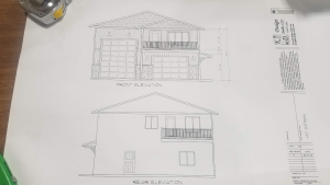
Long time followers of my column may be tired of reading my preaching from a pulpit about how fully engineered, code conforming buildings should be mandatory. Well, there is a method to my madness.

Now there are going to be naysayers who disagree, however there is actual proof of long term savings.

FEMA just released its 2020 National Preparedness Report (https://www.fema.gov/sites/default/files/documents/fema_2020-national-preparedness-report.pdf) presenting an updated, risk-focused approach to summarizing state of national preparedness, pointing to enforcement of updated building codes as key to lowering risks of damages from natural disaster. “Improving the resiliency of physical infrastructure requires more stringent building codes and standards, as well as innovative programs, policies, and procedures that encourage adoption and implementation of higher building standards,” the report stated. “Recent standards developed by the ICC (International Code Council – they publish our country’s building codes) are the gold standard of building code requirements. Florida’s experience with updated building codes demonstrates these cost savings in practice. After Hurricane Andrew in 1992, widespread damage to buildings across the state prompted Florida to adopt some of the strongest building codes in the United States. After 10 years of enforcement, the new codes reduced windstorm losses by up to 72 percent and paid for themselves in avoided losses within eight years.”

Considering building a new barndominium? Make a choice not only for monetary reasons, but most importantly for safety. Whether building yourself or hiring a contractor – I implore you to only build (or have built) from fully engineered plans. If hiring an erection contractor, familiarize yourself with those plans enough to know right from wrong. Due daily self-inspections during assembly to ensure those plans are indeed being followed, especially important in jurisdictions not requiring permits, or not doing structural site inspections. Even when inspections are required, even best of inspectors can miss something, so it is prudent to have your eyes involved.

If you do not feel confident of your own abilities to perform inspections, enlist the services of your engineer or an architect to do them for you. This money is well spent to protect your most valuable assets – the lives of you and your loved ones.

A Hay Barn Challenge

Seemingly every small town in America has one or more pole barn ‘builders’. Many of them are more jack-of-all-trades and masters of none. They frame a few houses, do a deck or two, maybe some interior remodels in winter months and along with this – a handful of pole barns.

Sadly, in my humble opinion, many jurisdictions have minimal (or no) permitting requirements for pole barns. This practice is extended even further when it comes to pole barns deemed to be for agricultural purposes.

Combine lack of structural knowledge (plus pooh pooing any need for an engineer) by ‘builders’ as mentioned above with not needing a permit and situations arise rife with a potential for possible calamity.

Reader KATHY in KIMBALL writes:

“We have a ranch in western Nebraska. There are two hay barns on the ranch, each is 64’x44′ with 20 foot from ground to bottom of trusses. These are constructed with the trusses on 4 foot centers on double top plate and V bracing. The side walls are fully sheeted and the end walls are open. Both hay barns are level and in good shape. However, we were loading hay out of one of the barns recently, with wind gusts north of 40 MPH and we could see the trusses moving slightly with the wind, the bottom of the columns were stable as they are encased in concrete.

My questions are: Would it add significant support to build an end wall on one end of each of these barns. If so, can Hansen provide the materials and tech support to build these end walls?

Is there anything else we can do to add strength and stability to these hay barns?”

Mike the Pole Barn Guru replies:
Post frame (pole) buildings work much like unibody cars and jet aircraft, it is their skin’s strength holding everything together. Here is a home experiment you can do to get a better idea (as well as an extended read): https://www.hansenpolebuildings.com/2011/12/lateral-wind-loads/

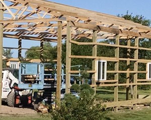
Your hay barns happen to be a worst case scenario when it comes to sound structural design of a post frame building: https://www.hansenpolebuildings.com/2018/03/ends-open-pole-barn-challenge/

What these buildings really need is to have both endwalls at least partially (if not fully) enclosed from eave to ground. If this is something you would entertain, we could connect you directly with one of our third-party independent engineers to determine if there is a practical solution to your situation.

Meanwhile, make sure your buildings have good replacement value insurance coverage and avoid being anywhere near them if wind speeds are at or beyond what you have already mentioned as causing your concerns.

Required Bracing or Not?

When he was just a tyke (I considered adding in ‘little’ however he was 3’6” tall on his second birthday) my son Brent asked me in all seriousness what it was like to watch space aliens building pyramids. While I am not quite as old as Brent may have thought I was then, it has been awhile since I was muddling through architecture school.

Architecture school, back in my day, was more about drawing pretty pictures than it was about how to make sure those pretty pictures would actually stand up. I do foggily remember having an eight a.m. structural design class at Montana State University (who in their right mind would schedule this class mid-Winter in Bozeman?).

ASCE (American Society of Civil Engineers) News had a summer guest contributor (Kyle Vansice) in 2012 who wrote about some of famous architect Frank Lloyd Wright’s work. Some excerpts include:

“However, I believe that Mr. Wright more likely stretched the existing construction techniques past their previous limits, possibly to a degree that diminished the factor of safety.”

“Unfortunately, Mr. Wright’s genius in architectural design was not matched by his understanding of engineering principles.”

“I believe the engineering behind his designs did not meet the exacting standards typical of a Frank Lloyd Wright space. Mr. Wright believed that the structures of his day were large, bulky, and overly engineered. He felt that it was possible to challenge conventional wisdom and beat back some of the conservatism in structural design. I think it is also true to say that while he knew existing limits were antiquated, he did not fully appreciate the actual physical constraints that his designs surpassed.”

“A good example of the need for structural remediation can be found in Mr. Wright’s riverside masterpiece, Falling Water. The iconic cantilevered portions of the home had at one point deflected close to seven-inches over their fifteen foot span, and analysis of the structure has revealed that the as-built design had placed these cantilevers dangerously close to their failure limits. Post-tensioning was eventually required to restore these portions back to their intended elevation and to prevent the sort of catastrophic collapse deemed inevitable (Tyler Meek, Fallingwater: Restoration and Structural Reinforcement).”

Falling Water

“Other well-known examples of Wright’s imprudence in engineering include the Guggenheim in New York and Taliesin; both of which encountered significant structural rehabilitation in order to restore serviceability and prevent failure.”

Mike the Pole Barn Guru comments;
Hansen Pole Buildings’ Design Studio Manager, Caleb Johnson posed this to me earlier this year:

“Have you ever heard of a county that requires knee bracing or corner bracing via comment below from one of my clients:

“Architects and structural engineers are telling me that all buildings need knee bracing, corner bracing, etc., which in a traditional stick build is the norm”.”

If one is to venture into a Building Department and not have engineer sealed building plans, it is fair license for them to add in any structural members they desire (whether structurally necessary or adequate). These hard working folks are generally not engineers.

Most architects (even our iconic Mr. Wright) have a limited grasp of how to structurally make things work and rely upon engineers to come up with designs to prevent failures. When it comes to fully grasping nuances of post frame design, there are a limited few engineers who have done research necessary to achieve practical design within limits of safety.

Knee bracing, for one, would be a rare feature of traditional stick building and when applied to post frame construction could be detrimental. (https://www.hansenpolebuildings.com/2012/01/post-frame-construction-knee-braces/).

Corner bracing (also referred to as diagonal bracing) in most instances is a redundant member, should an engineer actually understand principles of utilizing shear strength provided by steel skin (roofing and siding). Extended reading on diagonal bracing can be found here: https://www.hansenpolebuildings.com/2016/03/diagonal-bracing/.

There is a moral to this story – unless you are building using prescriptive tables within building codes (IRC or IBC), you are best to only build from fully engineered building plans, both for safety and cost effectiveness. If you are hiring an engineer to produce your plans, look for a NFBA member engineer (www.NFBA.org) with extensive post frame experience. Or, even better, invest in a complete building package including engineer sealed plans specific to your building, at your site and including extensive step-by-step instructions and unlimited free technical support from those with actual post frame building experience.

Questionably Designed Steel Truss Pole Barns

Being a member of numerous social media discussion groups, I see a plethora of photos of people’s new (or under construction) steel trussed post frame buildings. Most of these buildings are from Southeastern states where it appears structural building permits and plan checks are minimal or non-existent. This results in my receiving emails like this one from KEVIN in CULPEPER:

Hello! I am in the midst of building a pole barn, 40 wide x 90 long x 12 high posts.  We are using 6x6x16s and steel trusses. All is going well thus far my question is, would it be advisable to close in the long side walls and leave the ends open? Or leave all sides open? How does the wind load change in relation to this? I prefer not to fully enclose for now.  Also, what wind bracing would YOU utilize? Y braces, knee braces, X braces down the side walls, steel cables and turn-buckles spanning from gable peak to second post back? I’m in a windy spot.

THANK YOU in advance for any advice!” 


Mike the Pole Barn Guru comments:

While I appreciate your reaching out to me, these are questions best directed to your building plan’s engineer. He or she has structural design responsibility for your building. If somehow you do not have fully engineered plans, you desperately need one’s (an engineer’s) services. My best guess is 6×6 columns are overstressed in bending either with or without sides and will require an engineered repair. On typical post frame construction covering long sides and leaving endwalls open is pretty much a recipe for a failure as wind loads going into the top half of your sidewalls and roof are transferred through endwall sheeting to ground. No endwall sheeting means a tremendous load is being placed on those corner columns. Required bracing will be called out for on your engineer sealed building plans. Your building site happens to be an Exposure C – it is open to wind coming from one or more directions. Effectively this requires your building to be designed to resist roughly 20% more load from wind, than would a protected (Exposure B) site. This wind condition should be specified on those engineered plans.

I realize it is a huge temptation to throw hard earned money at questionably designed, bargain priced buildings. There is a reason their prices are so cheap – and if you are willing to sacrifice structural integrity for low price, there is nothing I can do to save you.

For everyone else – unless you are investing in a stick frame building following prescriptive requirements laid out within Building Codes (not just a handout from a Building Department) you should demand your provider supply fully engineered plans for your building – specific to your building’s features and your site. Anything short of this is an invitation to a future disaster site.

End Truss Overhang Dilemma

Reader ANDY in HAYDEN has an end overhang challenge. He writes:

“Hello Mr Guru. I’m building a 30x40x12 post frame with 18″ eaves. My trusses builder doesn’t build drop cord ag trusses for my gable over hangs. I was advised to lower the gable truss on the corner post to allow room for my on edge 2×8 purlinings  to extend over the top. I have a 16×10 garage door planned for below that over hang, will this method work. Can ladders be used?. I would appreciate your help sir. I know if I had the money I could have ordered one of your kits. Trust me I wish but I was born with a spork in my mouth and I’m just chipping away monthly on my project. Thank you for any help.”


Mike the Pole Barn Guru responds:

Most of our clients were not born with any sort of silver or plastic ware in their mouths – me either. While my brother and I did not realize it growing up, we were probably upper lower class in family income, but we were happy, our parents worked hard and we learned well from them. I have joked, “We were so poor our mother used to spray paint our feet black and lace up our toes”. It was not quite as bad – but Mother did go without socks for some time so we could have clothes.


Moving forward – there are advantages to investing in an engineered complete building kit package and not try to piecemeal. I have written about piecemealing before https://www.hansenpolebuildings.com/2014/03/diy-pole-building/. Ordering trusses can, as you have just found out, be far more difficult than it seems. https://www.hansenpolebuildings.com/2020/02/things-roof-truss-manufacturers-should-ask/

Financing is highly affordable, with some amazingly low interest rates and most suppliers have options available to delay some deliveries until you are more prepared for them.

Before you get carried away with an overhang, look at your engineered truss drawings. Guessing your building has a pair of trusses every 10 feet and a single truss on each end, it will need to be designed to account overhang weight plus any other dead loads and snow loads. To accomplish this, your end trusses should be designed with either one truss at five foot (plus a notation stating they can support an 18 inch end overhang), or have a spacing of 6’6″. If neither of these has occurred you need to contact your truss supplier for an engineered repair. It may be cheaper to use a double truss on one end (notching into corner and end columns, and purchase a correct new truss for the opposite end.

In any case, before there is any structural deviation from your engineered plans YOU MUST CALL YOUR ENGINEER. My suggestions are merely my opinion and are not to be construed as my supplying or practicing engineering. If you deviate from your engineered plans in any fashion, all liability for structural integrity falls directly upon you.

Measurements below are using this for a measure of eave height https://www.hansenpolebuildings.com/2015/02/eave-height-2/

Having taken care of loading issues in some fashion, you can lower your end trusses by 7-5/8″ to adjust for vertical component at a 4/12 slope (other slopes change this hold down dimension). This should put the bottom of your end trusses at 10′ 10-1/2″ for a 2×6 top chord truss (again at 4/12) or 10′ 8-3/4″ for a 2×8 top chord.

Bottom of your overhead door header should be at 10′ 5″ above grade (bottom of splash plank). This leaves 3-3/4″ only (2×8 Top chord) or 5-1/2″ with a 2×6 top chord for your overhead door header. Keep in mind, below an end truss this header carries absolutely no roof load. It exists merely to be a place for a row of screws or nails (non-steel sidings) and to be a place to attach an overhead door spring block to. If you were erecting a Hansen Pole Building, your end truss would be notched into your corner and endwall columns 1-1/2″ This allows for a 2×8 overhead door header to be installed above the top overhead door jamb and lapping onto end truss bottom chord 3-1/2″ (1-3/4″ with 2×6 top chord). Balance of end truss chords would have a 2×4 Std&btr nailed across to provide backing for siding and act as a stiffener resisting lateral loads and buckling.

Another advantage of a complete package is it should come with a detailed step-by-step assembly manual. At Hansen Pole Buildings this means 500 pages. 

Your engineer can verify if you can for 2×6 top chord truss place a 2×6 as a header between top jamb and truss, or move top jamb up 1/4″ and use a 2×4.

Ladder framing nailed or screwed to the face of end truss to create end overhangs is probably not structurally adequate and it could very well sag, if not fall off.

Best wishes.

Typical Wall Bracing Details for Pole Barns

There are many ways to permanently brace walls of pole barn (post frame) buildings. Most of these methods are utilized in buildings not designed by a Registered Professional Engineer (RDP). A RDP who has a great deal of experience with post frame building intricacies would first be looking at a structural design to utilize steel siding and roofing’s shear strength.

Hansen Pole Buildings’ independent third-party engineers use values obtained from actual full scale testing of steel panels done under supervision and auspices of engineer Merl Townsend: https://www.hansenpolebuildings.com/2012/08/this-is-a-test-steel-strength/. These test results, and those of other tests, are published in the NFBA (National Frame Building Association) Post-Frame Building Design Manual https://www.hansenpolebuildings.com/2015/03/post-frame-building-3/.

Recently reader JOSE from GONZALEZ asked:
“What are the typical wall bracing details for pole barns? Best locations?”

In utilizing steel skin strength, in many cases, needs for other wall bracing is eliminated. This makes for no extra expenses and ease of assembly. When wall bracing is needed, it is usually added closest to corners, where shear load forces are greatest.

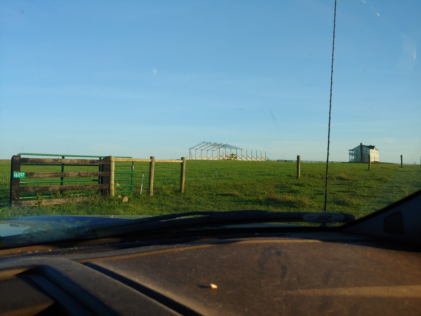
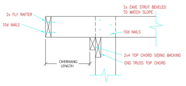
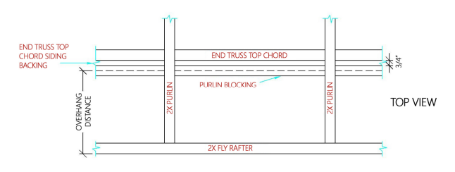
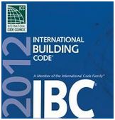
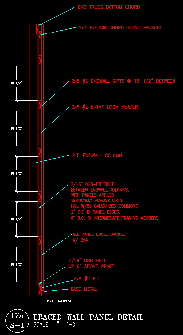
For cases where strength of steel skin is not adequate to support loads, the International Building Code (IBC) provides for wall panels to be braced by adding either Oriented Strand Board (OSB) or plywood. This most often occurs when a wall (or walls) have large amounts of openings (doors and windows) or in cases where buildings are tall and narrow, or very long (usually width of three to four times building length). An engineer can determine the applicability of this as a design solution. Installation of added sheathing is generally fairly simple and requires (in most cases) minimal extra framing materials.

X bracing is often found in non-engineered buildings and can be either of dimensional lumber or steel strapping. Actual effectiveness of either of these is limited by an ability to add enough fasteners to resist loading: https://www.hansenpolebuildings.com/2016/03/diagonal-bracing/.

Rural Renovators recently constructed a very tall post frame building where they utilized a triple set of 2×6 X bracing at building corners: https://www.facebook.com/ruralrenovators/videos/2089528207814164/

In any case, my recommendation for proper post frame building correct structural design is to only use plans designed by a RDP (engineer).

Overhead Door Header Problems

Overhead Door Header Problems (and More)


Reader MITCH in NASHVILLE writes:

“I recently purchased a property that the previous owner had just built a 30×50 pole barn on. It has foil faced double bubble on the roof and walls. I need to heat and possibly cool the space. What are the options for insulating the ceiling? The ridge is vented. There is no soffit and thus no vent there. The trusses are 5ft apart. Your all-seeing wisdom is appreciated.”

There are times I wish I was not what Mitch feels is “all-seeing”, because I find lots of problems in photos building owners are unaware of. 

Back in my post frame building contractor days I would go visit some of our newly constructed buildings, as time and logistics allowed. I generally had very, very good crews and we had an extremely high satisfaction rate from our clients. I would find things wrong (in my eyes anyhow) and send crews out to make repairs. More than once I would field phone calls from clients asking what was going on. They were perfectly happy with their buildings. I would explain to them they might be satisfied, but I was not!

Mitch’s photo shows a frequent challenge posed with post frame buildings where headers (in this case more appropriately known as truss carriers), support trusses between columns. I am not a gambler, but would place money on this not having been an engineered building. Just guessing, this builder used the same size truss carrier for all locations. Usually these truss carriers would be sized to support a single truss centered between two columns. Here, due to door location and width, this carrier supports two trusses, or double what it should have been carrying. 

Look back at this photo – there is a noticeable sag across overhead door top! This same sag will be evident along sidewall eave line outside.

Before any thoughts of insulating are considered, a competent professional engineer should be engaged to design an appropriate repair for this header. Engineer should be advised this header will also need to be capable of handling the weight of a ceiling without undue deflection occurring.

Moving forward, contact the roof truss manufacturer to get a truss repair to upgrade trusses to support at least a five psf (pounds per square foot) bottom chord dead load, with 10 psf being even better. Each truss should be stamped with information of who fabricated them.

Once header and truss repairs have been completed, use white duct tape to seal all gaps present in your roof’s radiant reflective barrier. Without these being sealed, there is a potential for warm moist air to get between barrier and roof steel and condensing.

Place ceiling joists on hangers between roof truss bottom chords every two feet. Your previously engaged engineer can verify if 2×4 Standard ceiling joists will be adequate.

Install vents in each gable end. Placed in the top half of each gable, a net free venting area of 360 square inches or more will be required for each endwall.

Hang 5/8” Type X gypsum wallboard on bottom of ceiling joists, leaving an attic access somewhere towards building center. Have a spray foam insulation installer apply closed cell foam along a two foot strip closest to each sidewall. Blow in fiberglass, cellulose or rock wool insulation across remainder of ceiling surface.

Responsibilities Where the Legal Requirements Mandate

Responsibilities where the Legal Requirements Mandate a Registered Design Professional for Buildings (Section 2.3 of ANSI/TPI 1)

MPC is Metal-Plate-Connected; RDP is Registered Design Professional (architect or engineer).

In preparation for specifying MPC wood trusses, every section of Chapter 2 and ANSI/TPI 1-2007 (NOTE: ANSI/TPI 1-2014 retains same language) standard should be carefully studied by the RDP. In preparing this article, we assumed that the RDP will view a complete copy of Chapter 2 for a full understanding. Specific sections selected for discussion are cited by paragraph and subparagraph numbers.

Under Section 2.3.1 Requirements of the Owner, we note three sections that can help prevent truss erection accidents, and in some cases improve in-service truss performance. Over the past two decades, industry safety documents recommended that for truss spans over 60 feet, the Contractor should “See a registered professional engineer” for temporary bracing information. In many cases, Erection Contractors failed to follow the advice, and some accidents and performance problems stemmed from inadequate temporary and permanent bracing. The new ANSI/TPI 1 standard now requires action by the Owner and RDP as given in the following paragraphs:

2.3.1.6 Long Span Truss Requirements.

2.3.1.6.1 Restraint/Bracing Design.

In all cases where a Truss clear span is 60 feet (18m) or greater, the Owner shall contract with any Registered Design Professional for the design of the Temporary Installation Restraint/Bracing and the Permanent Individual Truss Member Restraint and Diagonal Bracing.

2.3.1.6.2 Special Inspection

In all cases where a Truss clear span is 60 feet (18m) or greater, the Owner shall contract with any Registered Design Professional to provide special inspections to assure that the Temporary Installation Restraint/Bracing and the Permanent Individual Truss Member Restraint and Diagonal Bracing are installed properly.”

The importance of these new paragraphs to truss safety and reliability cannot be overstated. When executed by the Owner and RDP, these provisions for long span trusses should be effective in preventing truss erection accidents and ensuring in-service truss performance. “

Monitor Barn Truss Challenge

When All Else Fails a Monitor Barn Truss Challenge.

Monitor style buildings are a popular post frame building design (for background on monitor barns please read: https://www.hansenpolebuildings.com/building-styles/monitor-building-designs/). In most cases, design, ordering, delivery and construction of monitor buildings goes off without a hitch. On rare occasions a hitch glitch happens – so when all else fails I get to jump in.

Now I am highly qualified to solve post frame building challenges.

Why?

As a 1990’s era post frame building contractor, my company had as many as 35 building erection crews working at a time across six western states. We paid our crews very well, so we attracted a group of subcontract builders who we felt were a cut above most. Even with this, challenges could and would occur.

Over several years I have had DIY clients call and tell me, “You won’t believe what I have done, it may very well be among the worst mistakes ever”! I would relate my experience as a contractor and then assure them, “If an error could be made, one or more of my crews could figure out how to do it. Tell me your challenge and let’s work together for a solution”.

In these photos, please note on an end of these monopitch trusses it appears the pressed in steel connector plate at truss heel (low end of truss) is beyond the line of columns. At truss high end, seemingly just truss top chord is attached to column…leaving bottom chord hanging out in space!

Our client did not even realize a truss challenge had occurred. They had sent these photos in regards to an entirely different issue and we found it when looking at them.

Putting on my best Sherlock Holmes hat, it was time for some sleuthing. Our request transmitted to the truss manufacturer asked for a 12 inch overhang on these trusses. It turns out our truss people decided to put the overhang on high end of trusses, rather than low end. Sure enough, we missed this when we approved their drawings. Client (and/or his builder) somehow also missed this and installed trusses as shown in photo!

This one actually had a reasonably easy fix. Truss company’s engineer was able to design a repair using a solid block of 2×12 to fill in the space and attach truss and columns.

There exists a solution to every post frame challenge.

Oklahoma, Is it OK?

Oklahoma, Is It OK?

Last weekend my lovely bride and I attended an event hosted by her first husband’s sister and her husband. Event purpose was to celebrate this couple’s upcoming 40th wedding anniversary.

Adding to this fun, at least for me, was a new Hansen Pole Building being erected onsite (D.I.Y. husband doing some nice workmanship). Like most new construction this attracted a fair number of looky-lous who wanted to check everything out and offer their ‘armchair expert’ opinions.

One of these lookers was aforementioned husband’s brother, who (as I later found out) had his old pole barn collapse due to snow last Winter. Rather than contact us about a replacement building, he ended up buying a post frame building to be delivered from Oklahoma (keep in mind we are in Northeast South Dakota).

Now I happen to know these folks in Oklahoma who provided this kit package. I hadn’t visited their website in quite some time, so I went browsing.

Here are some things I found:

“Building codes and permits

In our recent annual post-frame construction industry survey, one of our questions to builders was about code enforcement in their areas. Of the 134 post-frame builders who answered this question, 55% said they have needed on occasion to change their construction to meet a code. Codes can be problematic if not clearly understood. Start with your local planning and zoning office or your local building inspector. They will be able to tell you the standards for your community.

Know the rules in your area:

  • Some cities will not allow a steel skin building – you must have a brick veneer.
  • Almost all residential areas will have a setback requirement, meaning the building must be so many feet from the property line.
  • Many neighborhoods have a restriction on how tall you can make the building.
  • Many areas want to inspect a building at each stage of construction, starting with the depth of the holes, then they will inspect the wooden framework, then the completed structure.
  • Some communities insist on bolting the trusses in place, adding hurricane clips, beefing up the top plate, digging the holes deeper and providing longer poles or adding gravel or a concrete footer in the hole.

Bonus Tip: Some local code expectations may seem over-engineered when it comes to equating cost with necessity. In our view, codes generally foster a better quality building and we have found it is best to give the inspector what he or she wants. Life, and your project, will go easier that way.”

Now I agree total with starting a journey to a new post frame building with visits to your local Planning  (https://www.hansenpolebuildings.com/2013/01/planning-department-3/) and Building (https://www.hansenpolebuildings.com/2013/01/building-department-checklist/) Departments.

What amazed me was “55% said they have needed on occasion to change their construction to meet a code”. Thinking back over nearly 40 years of post frame buildings, I can only think of two sets of circumstances causing a change in construction to meet Code. First – not submitting plans prepared by a RDP (Registered Design Professional – architect or engineer), second would be not having correct design criteria (snow, wind and seismic loads, along with frost depth) provided.

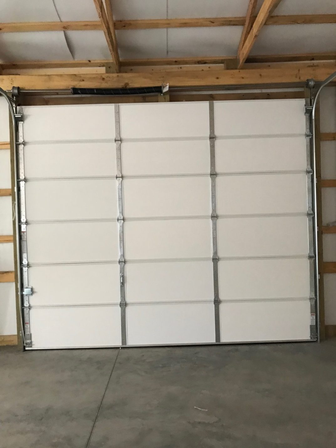
In my humble opinion, a majority of these builders who had to change their construction were probably not building Code conforming structures! Think about this if you are considering investing in a post frame building from ANY builder.

While some jurisdictions will not allow steel roofing and/or siding, I have yet to have any demand a “brick veneer”. There are numerous alternatives to steel, they just happen to be less economical and less durable.

Only insistence from communities regarding how buildings should be assembled comes from those who have prescriptive requirements for non-engineered pole buildings. Read about challenges of prescriptive requirements here: https://www.hansenpolebuildings.com/2012/02/prescriptive-requirements/.

Path to best value for one’s post frame building investment nearly always involves having RDP sealed plans. Make everyone’s life easier (you, your building kit provider, any contractors, as well as your Building Department) and insist upon only using RDP sealed building plans. Headaches saved, will be yours!


What To Do With an Old Dollar General Pole Barn

What to Do With an Old Dollar General® Pole Barn

In the fall of 2016 the town of Reading, MI purchased the pole barn which had previously been the home of a Dollar General® store. The original plan was to convert the pole barn into a new city hall, but, after seeing the estimated price tag the idea was set aside.

The city’s maintenance man, Bob Jepsen, suggested tearing down the walls, replacing the building’s leaky roof and converting the building into a pavilion. It turns out the city’s planning commission thought this would be a great idea and held a public meeting to discuss.
In the early days of railway transportation, the brakemen rode in the last car of the train – the caboose (seen many of these lately?). He had one of the deadliest jobs in America, as the brakeman had to work from the tops of the railway cars in all sorts of weather.

In the case of the old Dollar General® pole barn, I am going to act as brakeman on the runaway train which is the remodel of the building into a pavilion.
Tearing the walls off of an existing post frame (pole barn) building sounds relatively easy – and from a labor standpoint it may be. Where it all gets dicey is when it comes to structural engineering.

When a post frame building has its walls removed, the columns (posts) now act as cantilevers. They are functioning similar to a diving board, where the end is very flexible. With the walls on the building, the columns are, in most cases, acting as beams supported at one end by the ground and the other by a relatively rigid roof diaphragm.

The difference in the loads which the columns must resist are increased by a factor of four without the walls present, as the posts become the sole structural members for transfer of wind loads from the roof to the ground. This potentially not only impacts the design of the columns, but also of their embedment into the ground.

Whether it is this particular Dollar General® pole barn, or any other post frame building where exterior walls are being considered for removal, a RDP (Registered Design Professional – engineer or architect) should be engaged early on in the process to make a determination as to what upgrades are necessary to result in a structurally sound building.

18 Foot Span Roof Purlins?

The Possibility of 18 Foot Span Roof Purlins?

Reader CHRIS writes:
“I have a building I want to build but I am not able to add the height I need on the side walls.  My plans are 24 deep by 30 wide with 8 foot walls.  Roof trusses would be 24 ft.  My problem comes from overhead power lines.  They are right in my way.  I really need 10 or more feet of ceiling.  The wall structure will be 2×4 residential style build with double top and bottom boards this should spread the weight out on the concrete well.

The span of the 1st section (north side), would need to be 18ft.   If I used a triple truss at 18 ft. and 2×8 purlins would I be able to get this to work.  I will be using a metal roof the 30 ft. wall will have a 16 ft. door and 9 ft. door Eve entry.  I know it’s not optimal.  But to get a lift inside the garage it will be a must to get this span.  Also my garage door will follow the roof line. In the 18 ft. area it will be hung from the purlins.  A winch will be used as an opener.  Also attached to the purlins but boxed to prevent movement.”

Mike the Pole Barn Guru writes:
In most jurisdictions you are not allowed to build under power lines – you need to be consulting with your local power company and your Building Official first. Even if it is allowed, you would be wise to have the lines relocated, or buried so as to not have a future issue. A live wire comes down on your nice new steel roof and poof!

Depending upon your roof load and wind load, it might be possible to span 18 feet between trusses with purlins, however they are probably going to need to be larger than 2×8. With the proper truss design, it might very well be able to carry the end of the purlins with a double truss.

What you are proposing is well outside of the prescriptive portions of the Building Codes, so whether stick framed or post frame (post frame will be far more economical) you should be utilizing the services of a RDP (Registered Design Professional – architect or engineer) in order to make sure you have a new building which is adequately designed to support the imposed loads.

Both Ends Open, Pole Barn Wind Load Challenge

The Both Ends Open, Pole Barn Wind Load Challenge
There are plenty of people who just do not understand the basic concepts of how wind loads are transferred through a pole barn (post frame building) to the ground. Included amongst these would be those who desire buildings which are enclosed on both long sidewalls and open on both ends. This is one of the worst possible design concepts one can come up with in a new post frame building.

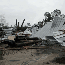
Of course somewhere along the discussion between the Building Designer and the client this statement always seems to come up:
“Well Joe Blow has one down the road and his is still standing”.
My response to this is – “Joe has just been phenomenally lucky”.

In my years living in Eastern Washington, we made numerous trips from Spokane to Seattle. Driving across Interstate 90, one passes through the towns of Moses Lake and Ellensburg. This is prime grass growing country, where numerous hay storage buildings have been constructed over the years, with both ends open. The majority of these now have complex systems of braces and/or extra diagonal columns added to their sidewalls in attempts to maintain them standing vertical. More than a few of them only remain standing up because they are full of hay – the contents alone are what is keeping the buildings standing.

I’ve hashed through this challenge in the past, however it is apparent too few people have read and grasped the situation (read more here: https://www.hansenpolebuildings.com/2017/04/open-endwalls-hay-barn/).

For those of you who enjoy audience participation, please go find an empty shoe box and a pair of scissors.
Remove the lid (and the shoes) from the shoe box. Place it open side down on a table top. Push down on the box – pretty stable, isn’t it?
Next, cut both of the narrow ends completely out of the box. Again place it open side down on the table and push on it…..
Flat as a pancake, isn’t it?

The very same concepts work to keep buildings standing. Remove too much or all of the ends and the building does a fall down, goes boom.

Just because Joe happens to have a building standing which sound engineering practice says it should not be, does not make it right. Most folks are going to make a significant financial investment into a new post frame building and my personal preference is for them to not have their insurance company paying to replace the building.

A Retro-Fit, Truss Support? and Sliding Door Installation

The pole barn Guru looks at a Retro-Fit, truss supports, and installing a sliding door.

DEAR POLE BARN GURU: I have a question about Retro-Fit insulating my pole barn. I live in Southwest Michigan and bought my house with an existing 40’x60′ building, just used for storing farm equipment before I acquired it. Steel roofing straight to the roof purlins and steel siding straight to the wall purlins. Can I put a metal ceiling in with blown fiberglass insulation above and metal walls with Batts between the inside wall and outside wall, or do I need to have some sort of vapor barrier? MITCH in MICHIGAN

DEAR MITCH: First things first, in order to retro-fit the trusses, confirm the trusses are capable of supporting the weight of the steel liner panels and insulation. Most post frame building trusses are not designed to support a ceiling. There should be a stamp on every truss which identifies the truss manufacturer as well as the design loads. You need a minimum three psf (pounds per square foot) bottom chord load to support the ceiling. If it is less, and you can contact the truss manufacturer who should be able to provide an engineered repair to upgrade the trusses, for a nominal fee.

You will need to have some form of thermal break below the roof steel – my choice would be closed cell spray foam. On the walls, you should really have a building wrap between the steel and the framing, however an inch or so of closed cell spray foam would work, filling the balance of the cavity with unfaced fiberglass, then a well sealed vapor barrier on the inside.


Engineer sealed pole barn
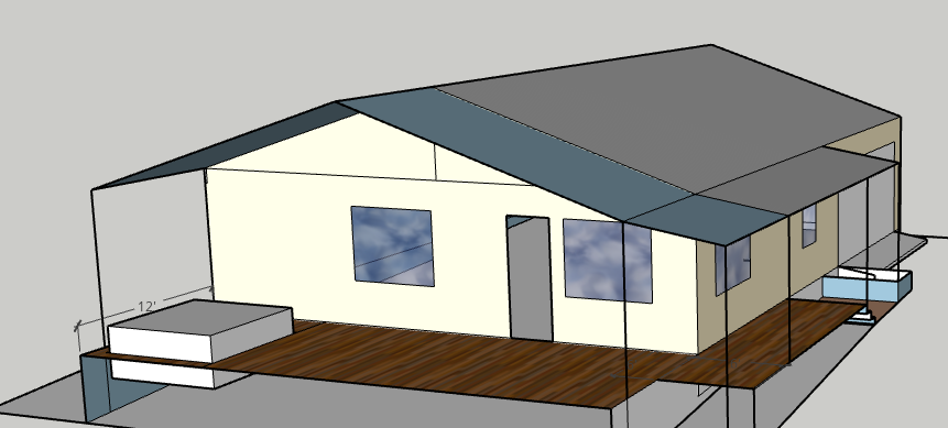
DEAR POLE BARN GURU: Pole Barn Guru, do you have to have girt under end trusses. End trusses setting on 2×12 from header and nailed to 6×6 pole with 2×6 blocking below trusses 24″o.c. sheated header 3 2×12 notch blocked and clipped. STEVE in CHEYENNE

DEAR STEVE: In order for me to answer your question, I would need to see the engineered plans for your building. If you are unsure of how to determine from your plans, you could contact the engineer of record who designed your building and ask him or her.

DEAR POLE BARN GURU: On a sliding 4×8 walk in door, on the barn exterior are all 4 sides flat or is the top out the thickness of say 1.5 inches? If it is out will it not seal? If all is flush with it not roll easy? Joe

Figure 27-5

DEAR JOE: The sliding door track needs to be mounted to a ‘track board’ which is typically a 2×6 placed on the face of the sliding door header. This puts the top out 1-1/2″ which allows the door to be able to slide past the adjacent siding without banging against it. Sliding doors do not and will not seal air tight, so this should not be an issue unless you had some sort of unrealistic expectations.

Pole Barn Footings

Some things in life amaze me – magicians are one of them. I have no idea how the do what they do, but I am totally fascinated by them (you can read about my college experience with a magician here: https://www.hansenpolebuildings.com/2014/08/lumber-bending/). One of the other things which amaze me are how clients will invest tens (or hundreds) of thousands of dollars on a new post frame building, only to cheap out on the footings!

Anything of high quality requires a good foundation.  In post frame buildings, the measure of a good foundation’s investment is small in comparison to the overall picture.

Reader CHRISTINE from SPOKANE writes:

“We see all these posts about footings. It seems here they just pour concrete around post with no footings. Is that due to the nature of our rocky soil. Our posts are in the ground, no footing and ready for concrete, architect plans, say “bottom of all footings to bear on undisturbed ,native, inorganic soil 1′ min below grade. Extend all footings 4′ min below finish grade.” Did I assume wrong and he’s calling for an actual footing? TYIA! ASAP”

Dear Christine;

For years we designed our post frame buildings without a concrete footing below the columns, instead relying upon the concrete encasement around the posts to adequately bond to the pressure preservative treated column. The bond strength between concrete and wood is documented and more can be read about it here: https://www.hansenpolebuildings.com/2013/04/pole-barn-post-in-concrete/. There were some Plans Examiners who did not look kindly upon this as a design solution.

The Building Codes do specify the requirement for a concrete footing, and as such we moved several years ago to a design which placed eight inches thick of concrete below the column.

As an architect designed your building and placed his seal upon the plans, you are obligated to construct the building per his/her solution. There should be a detail on the plans which shows exactly what the architect had in mind. If there is not, request a clarification as this is something you paid for in your fee for the work.

Mike the Pole Barn Guru

Looking for a post frame building with a column embedment design which both makes sense and works structurally? If so, only consider a building which comes with plans done specifically for your building, on your site, and sealed by a Registered Professional Engineer.

Spot the Post Frame Problem

Spot The Post Frame Problem – Reprised

In our last episode, I left you all with a cliff hanger. I did clue you into it being a structural issue, which rules out our builder in the air with his safety harness hooked to an invisible sky hook.
While you all ponder the photo and look at it closely, I will mention a few items which are not necessarily a problem, just maybe not what I would call “best practices”.

Note the trusses. One is on each side of the column. Chances are good this builder is marketing his product as a double truss system. What they actually have are two single trusses spaced 5-1/2 inches apart. These trusses do not act as a pair, because the blocking between them will not transfer the load from one truss to the other.

Each of those trusses is bearing on a block. The trusses are depending only upon the nails or bolts driven through the end of the truss and the blocks to keep them up in the air. There was a time when I did buildings this way also. Until the day I saw a set of trusses and the blocks below them driven down the sides of the poles by excess snow! They were only stopped from hitting the ground by the vehicles which were crushed inside.

Paddle blocks – if you do not know what they are, or their potential for future challenges, you will want to read here: https://www.hansenpolebuildings.com/2012/05/paddle-blocks/.
Okay, time to get serious here. Look at all the pretty wall girts. Nailed flat on the outside of the columns. They all fail due to not meeting the required deflection criteria set by the Building Codes: https://www.hansenpolebuildings.com/2012/03/girts/.

Now the particular jurisdiction where this building is being built has their own prescriptive solution to this problem. I’ve railed against prescriptive requirements in this forum previously: https://www.hansenpolebuildings.com/2012/02/prescriptive-requirements/. Look closely at the wall in the back of the photo. Look at the right hand bay. Note how every other wall girt has another board nailed to it to form an “L” as a stiffener. Truly wonderful as this solves the deflection issue for these particular girts only. The girt in between, without the stiffener, still fails!

Again I preach and beseech – please, if you are going to construct or have constructed for you a new post frame building, only do so with plans which are design specifically for your building and your building only, which are designed by a Registered Design Professional (architect or engineer).

The Argument Against Building Codes

The Argument Against Building Codes

The argument against building codes isn’t a haphazard attempt to loosen restrictions. Instead, it’s often made by experienced contractors and other industry veterans who are frustrated by certain trends and aware of hazards or risks the general public may not realize.

When construction teams “build to code,” what does this really mean? Unfortunately, it often means complying with the bare minimum of legal requirements.

Building-Plans2Ponder this one carefully – “the bare minimum”. Or, in other terms just enough to get by. Would you prefer to fly in jet aircraft designed by engineers who were 4.0 students in college, or ones who barely scored high enough to graduate? How about buying a new car, with a highest speed capability which is equal to the speed limit, and no greater?

No reputable builder or building supplier will defy codes intentionally, but if the only goal is to make sure a property isn’t illegal, they may not have incentive to go above and beyond with quality or safety.

You don’t have to see into the future to know what happens when only the bare minimum requirements are followed. Martin Holladay, who serves as a Green Building Advisor (GBA) Senior Editor, points to historic Vermont homes with rotten sills, undersized rafters and bulging foundations as examples of corner-cutting craftsmanship which only barely complied with the building codes of the time.

Of course, safety is still the primary purpose of building codes. However, because construction crew training isn’t required and building owners aren’t necessarily savvy about the best materials and building practices, construction teams can continue to neglect the quality of their work.

What can the average post frame (pole building) future building owner do about it?

Don’t buy to minimum standards.

Repeat – don’t buy to minimum standards.

Just.  This.  Simple.

Oftentimes the investment to upgrade climactic loads (wind and snow) to standards more rigorous than the minimums is negligible.

I see lots of proposals from pole barn suppliers and builders, which do not even specify the design loads of the buildings being proposed! And even more amazing – PEOPLE BUY THESE BUILDINGS!!

Don’t be a fool, for a fool and his money are soon parted. Know what the minimum loading requirements are (https://www.hansenpolebuildings.com/2013/01/building-department-checklist/).

Demand to have the design wind and snow loads specified on any quotation and most certainly upon any order.

Ask – how much more would it be to increase the design wind speed by 5, 10 or even 20 miles per hour. Ask – about the extra investment to increase snow load capacity.

And after all is said and done, don’t invest in a building which does not come with plans and calculations specific to your building, at your site and sealed by a registered design professional (RDP – engineer or architect).

For more reading on engineered buildings: https://www.hansenpolebuildings.com/2011/12/engineered-buildings/

Storage in Trusses

Welcome to Ask the Pole Barn Guru – where you can ask questions about building topics, with answers posted on Mondays.  With many questions to answer, please be patient to watch for yours to come up on a future Monday or Saturday segment.  If you want a quick answer, please be sure to answer with a “reply-able” email address.

Email all questions to: PoleBarnGuru@HansenPoleBuildings.com

DEAR POLE BARN GURU: My shop is in a 30×40 pole barn. I would like to put storage up in the trusses, and have some of the shelves that hang from the ceiling also (really there is no ceiling right now, just the trusses and roof). The trusses span the 30ft and I am worried about putting too much weight on them. I really would rather not have any supports in the middle of my floor…I was wondering if I could just sister up to the truss with some 2x6s or bigger to strengthen them…or should I just limit my upper storage? ONLY IN OHIO

DEAR ONLY: Unless specifically ordered for light storage loading, pole building trusses are rarely constructed so as to support any weight from their bottom chords other than limited electrical and lighting.

As you are considering “beefing up” the existing trusses, you should consult with the company which manufactured the trusses. There is typically a stamp on every truss with the truss company’s name on it. For a nominal fee, they can usually provide an engineered “repair” to upgrade your trusses.

In the event the truss company cannot be located, a Registered Design Professional (RDP – engineer or architect) should be hired to design a repair for you.

Only with one of these two solutions would I be able to recommend placing anything for storage in the truss system.

An alternative may be to build a raised “loft” floor in the building, at the level of, but not supported by the trusses. Again, this is a design best accomplished by a RDP.

DEAR POLE BARN GURU: Hello, I am contractor assembling one of your pole building kit packages.
Would you send me details for flashing the building please?
Need:
-Corner flashing.
-End capping the cut ends at top.
-Where do the corrugated foam strips reside?
-Roof panel overhang on the sides and ends.
-Door trim flashing

Thank you, WISHING IN WASHINGTON

DEAR WISHING: All of these are covered in depth in the Hansen Buildings Construction Guide which was provided to your client after purchase. If your client has not shared it with you, you should ask him for the big white binder which was sent to him. Every piece of trim has a diagram showing what it is along with the code used by the steel company. Detailed drawings show where each piece goes on the building.

Building Code: Things Which Make My Head Hurt

International Building CodeThe International Building Code (IBC) is the resultant of years of practical experience and sound engineering practice. The authors are a collective group of Building Officials and engineers, whose mission is to protect the safety of those who will be utilizing the structures built under the auspices of the Code. For practical purposes, every word, of every section of the Building Code has been scrutinized, analyzed, hashed over and rehashed to produce what can only be considered as a magnificent work. Even at this, amendments, additions and subtractions are proposed and made or rejected, providing an updated version every three years, which reflects changes which have come about from better science and research.

The Code also allows individual jurisdictions, to make local amendments to the Building Code. Oftentimes this is done without a sound engineering basis, or research to confirm the reasoning behind the amendment(s).

I am going to now pick upon a single permit issuing jurisdiction. This unnamed county has, as is their right, adopted the following:

15.16.060 Post Frame Structures (pole buildings).

A. Post frame structures over twelve hundred (1200) square feet in area shall be designed by a professional, licensed by the State of (Name Withheld) to design such buildings. The licensed professional shall affix his/her certification and signature to the design, including design drawings and details, specifications, and calculations. Any changes to the design, drawings, details, specifications, and calculations during review or construction shall be prepared and certified by the licensed professional designer of record and submitted for approval of the building official prior to incorporating such changes into the work. The minimum design criteria for post frame structures are as follows:

1. Minimum snow load is thirty-five (35) pounds per square foot (PSF). Reductions in live load/snow load are not permitted.

2. The minimum roof purlin dead load is 5 PSF.

3. The maximum total load deflection is:                       

 a. With ceiling: L/240

 b. Without ceiling: L/180

4. The maximum wall wind load deflection is L/120.

We recently had a plan review done, in this county, and the Plans Examiner/Building Inspector threw in this curve:

“Our standard design for accepting engineered plans for pole buildings over 1200 square feet, require that purlins/girts are spaced no more than 24” O.C.  Your plans call for girts spaced at 31 5/8” and purlins at 29 ¼”. “ 

After some discussion with the Plans Examiner the resultant was (as relayed from one of our owners):

They don’t have a 24” oc girt and purlin requirement – just the change to deflection that we looked at. His (building officials) reasoning was ‘experience’ – that engineers use code to under design buildings.

I will only address issues which I feel are either contrary to the Building Code, do not make sense from an engineering standpoint, or do not have a rationale under the Laws of Physics.

Minimum snow load. The Code addresses how to calculate Pf (flat roof snow load) and Ps (sloped roof snow load) based upon Pg (ground snow load) as well as factors such as Is (building importance), Ct (temperature factor – is building heated or not), Cs (sloped roof factor), and Ce (roof wind exposure factor).

Picking an arbitrary roof snow load, leads to the possibility of either gross over design (causing more cost to the building owner) or gross under design (leading to a possible failure).

As espoused by this jurisdiction, a roof for an Essential Facility (think fire station), which is unheated, has a 4/12 slope shingled roof, and is protected from the wind, would have the very same load as a heated storage building with an 8/12 pitch metal roof, which is exposed to the wind. Common sense says this is just not the case.

Minimum roof purlin dead load of 5 psf. The dead load should be set by the RDP (Registered Design Professional – architect or engineer) who designs the building to reflect the actual imposed loads. As 60% of the dead load is used to calculate the wind uplift forces on the building, an arbitrarily high dead load could result in the under design of the connections between purlins and trusses, as well as trusses and columns.  Potentially this could result in a design, by statute, which results in an overstress of these connections.

In reality 2×6 roof purlins at 24 inches on center, supporting a 29 gauge steel roof induce an actual dead load of about 1.5 psf (pounds per square foot). The 5 psf requirement is 333% higher than reality.

The Building Code allows for purlins supporting a light gauge steel roof to have a deflection of L/150, rather than the stiffer L/180. Deflection criteria have nothing to do with the structural integrity of the roof, merely esthetics under high loads.

The Code allows for wall girts supporting light gauge steel siding to have a deflection of L/90, rather than the stiffer L/120, as long as brittle finishes (such as plaster or drywall) are not being supported. Again deflection criteria have nothing to do with the structural integrity of the siding, merely esthetics under high loads.

Creating criteria which are counter to the majority of the jurisdictions in the country only creates confusion for RDPs, building providers and contractors, as well as increasing costs (without reciprocal benefits) to building owners. These criteria appear to be arbitrary and capricious in penalizing post frame construction against other forms of building construction.

If the feeling is the Building Code allows RDPs to under design buildings, then the jurisdiction should move the International Code Committee (along with providing rational proof as to why) to change the IBC. If snow load is their concern, the utilization of higher Pg values than have ever been historically seen (while not a reality), would allow for a uniformity of calculations by registered engineers.