Reason You Go With Engineered Prints
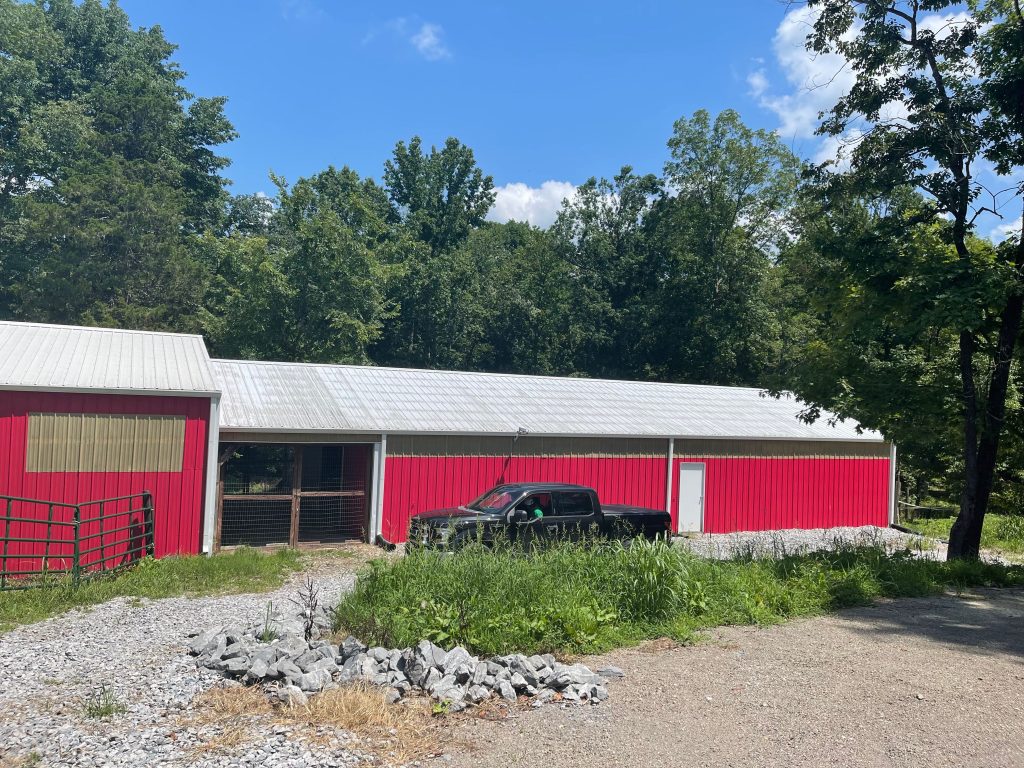
Yes, I know some of you gentle readers are offended by my harping on how important it is to build only from site specific fully engineered plans. Well, here is a case study.
Reader AARON in CARBON HILL writes:
“Reason you go with engineering prints. My contractor said it’s how we always do it. Well after they fell he said we need to discuss payment on the work I’ve done I paid for all material up front. I’m not paying c**p he should pay me for the lost and damages.”
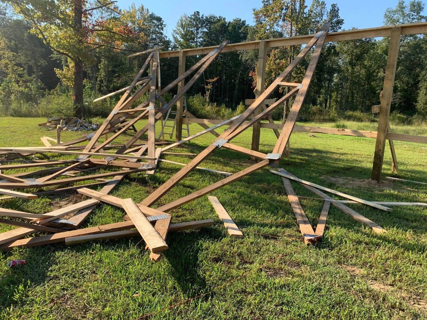
As far as engineering goes, it appears columns have an unsupported length of under 131 inches.
Why would this be important?
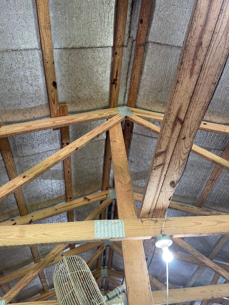
For a roof only building, such as this, columns are carrying all of the bending loads from winds. Sound engineering practice, says wood column’s least dimension (5-1/2 inches) x 50 divided by Ke (2.1 in this instance) equals maximum unsupported length.
5.5” x 50 / 2.1 = 130.95”
K factor approximates length a column actually buckles at. This effective length can be longer, shorter or exact depending upon rigidity of supports. As a roof only structure has no means to transfer horizontal loads through endwall sheathing, columns act as cantilevers (think diving board). For a building with sufficient endwalls Ke would be 0.85 (makes a huge difference).
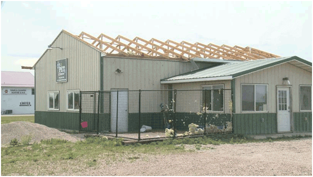
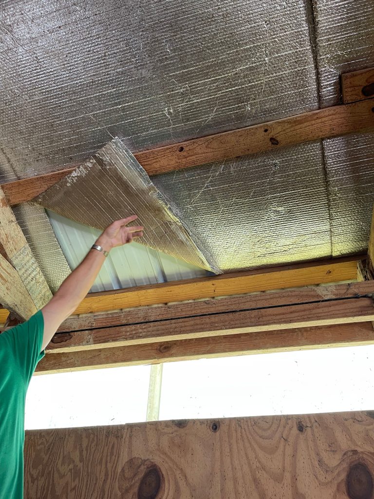
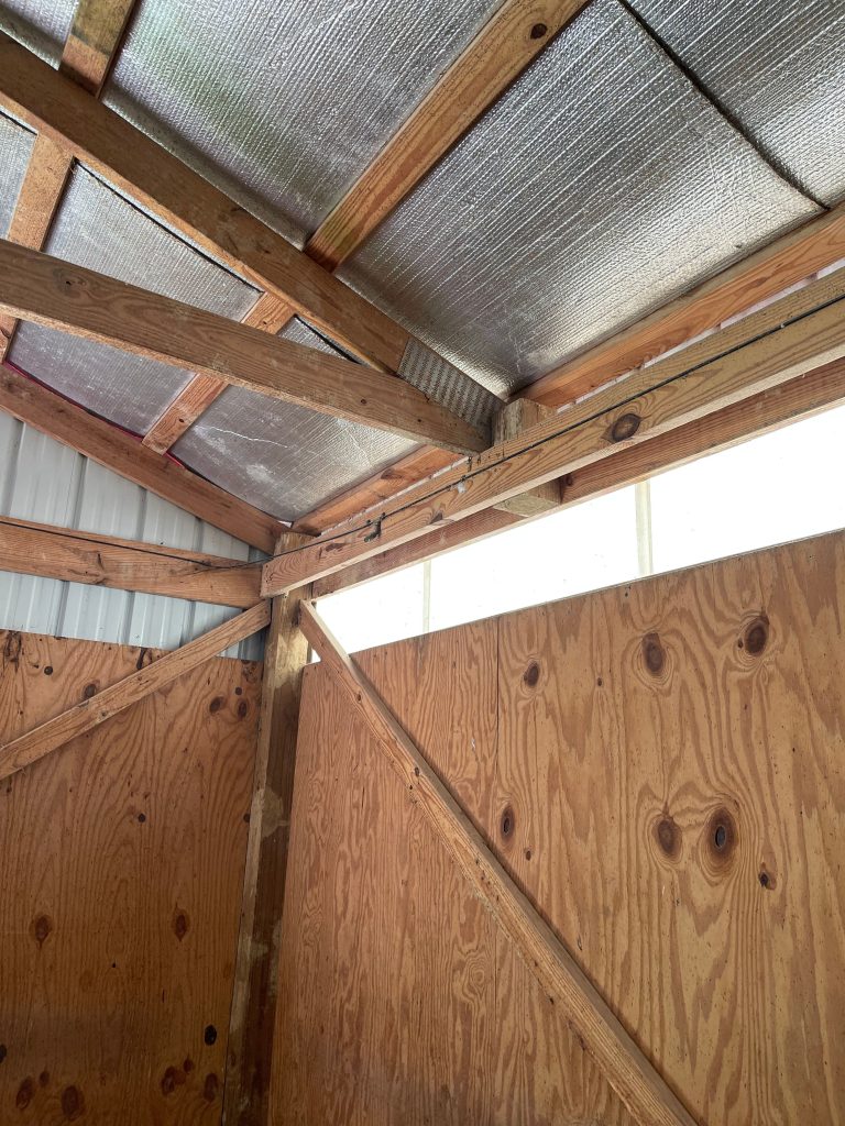
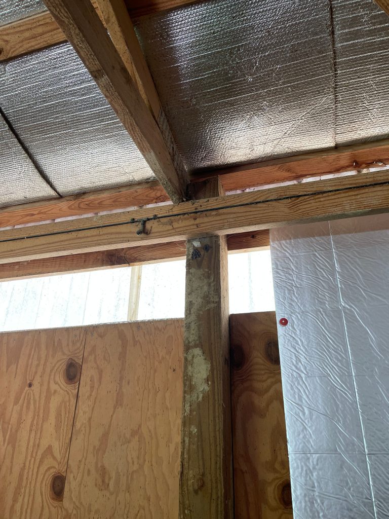
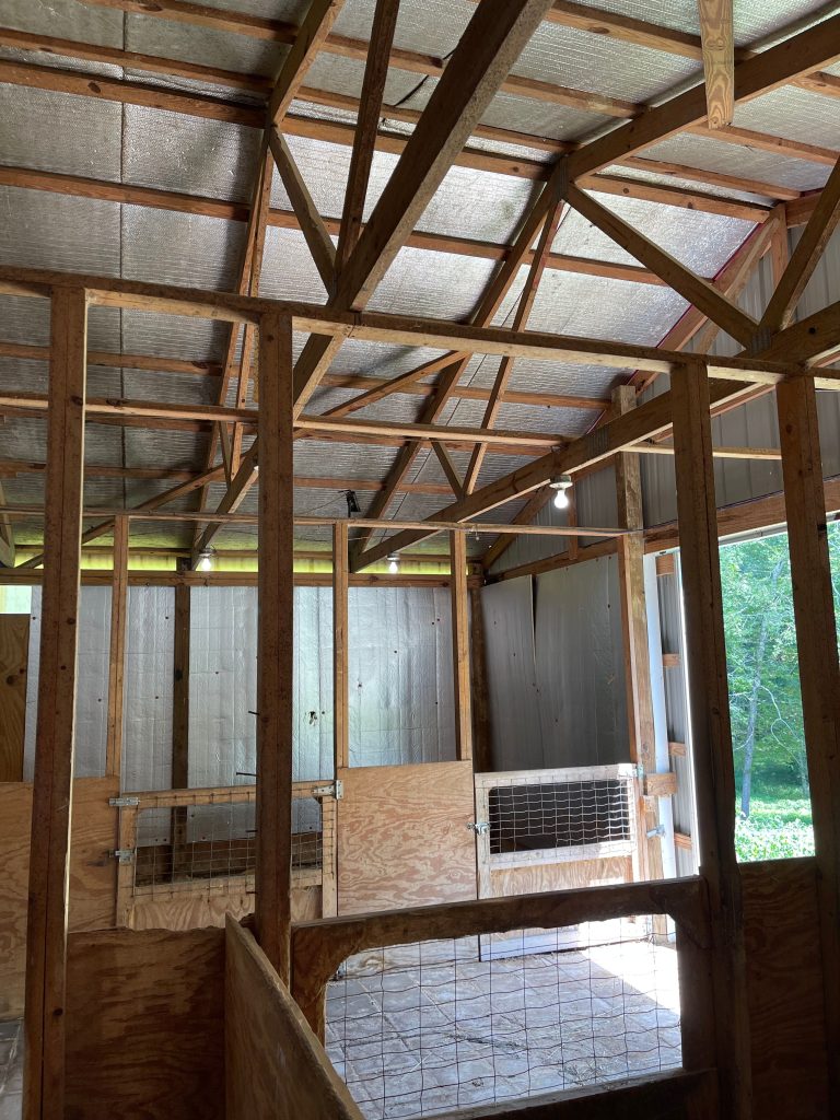
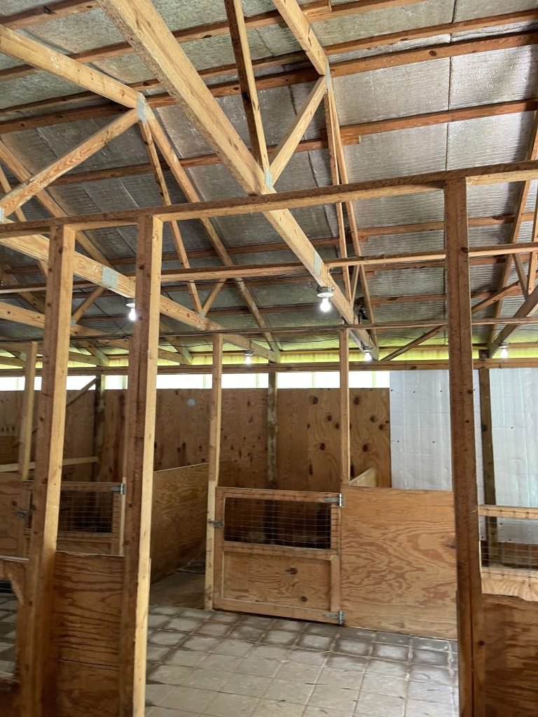
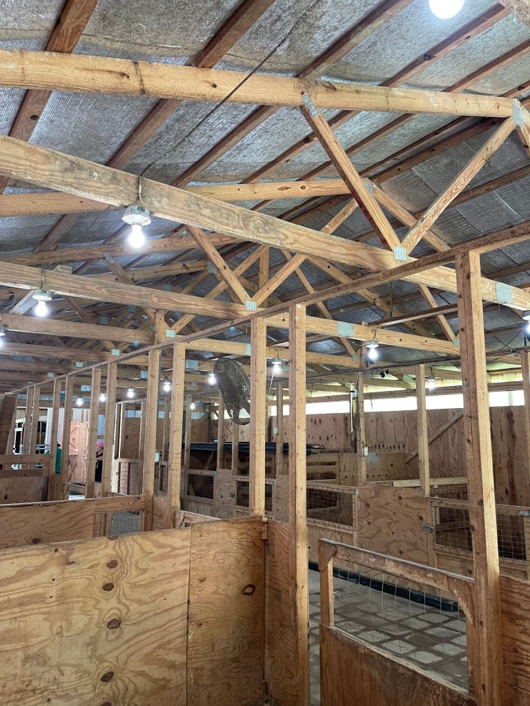
Truss carriers appear to be sketchy, however not having site loads, nor size, grade and species of them, it is impossible to verify (and none of them appear to have failed in photos provided).
What is absent? Temporary and permanent truss bracing.
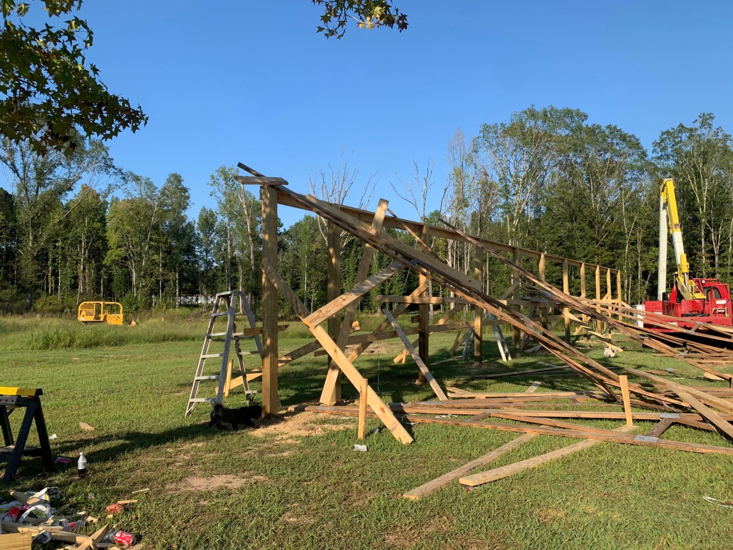
I have expounded on how important temporary truss bracing is previously (https://www.hansenpolebuildings.com/2014/12/temporary-truss-bracing/). I advised Aaron this appeared to be the cause of his now firewood. Also – this one is on his builder, who has some cajones asking to be paid when he caused this mess.
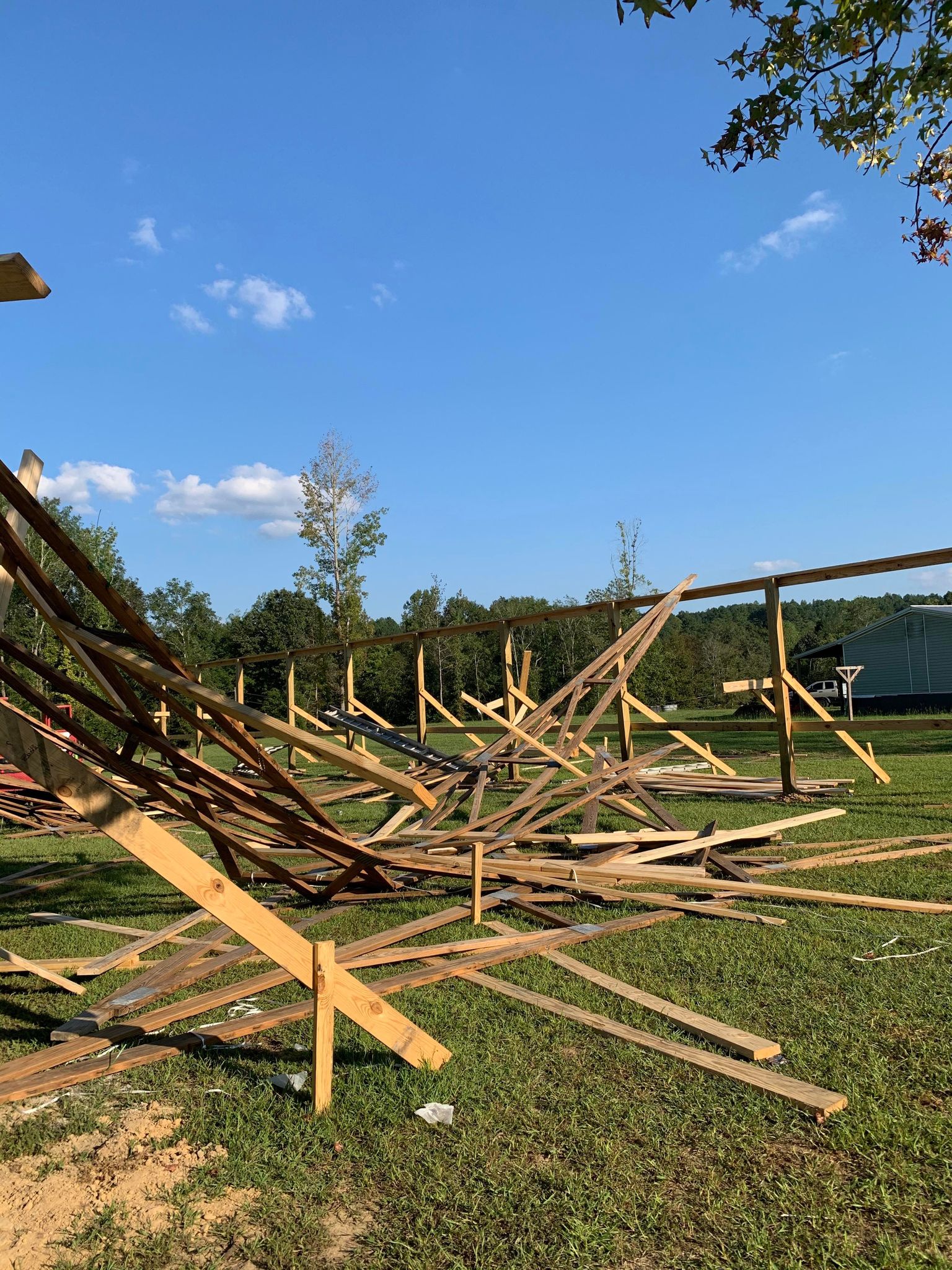
AARON responded, “Yep thanks I just thought if anyone wanted to see what happens when your contractor doesn’t follow the prints. Feel free to share with anyone. We will be ordering a new building kit and go with a contractor with more references. Thanks.”
Currently, there is such a shortage of builders, every Chuck-With-A-Truck, a hammer, circular saw, big dog and loud radio seems to think they can hop in and make big money. Don’t be caught in Aaron’s situation – always thoroughly vet any contractor https://www.hansenpolebuildings.com/2018/04/vetting-building-contractor/.
 Because I am not a Registered Design Professional, I can’t engineer your new post frame building for you. And, if I was, I most certainly would not be doing it for free. Typically an engineer should be compensated somewhere in the area of 8 to 12% of the value of the project, depending upon how involved they have to be with it, as well as if a visit (or visits) to the site are included.
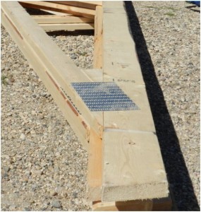
 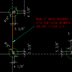 Some commentary – there are wet set brackets made specifically for post frame buildings. I would recommend you invest in them rather than trying to fabricate (or have fabricated) your own, unless they were designed by your RDP and inspected by him or her after production. For Clay soils, the Building Code allows a value of only 1500 psf – any greater values should be used only if an onsite soils test has been done by a registered engineer, else you are at risk of settling issues. See Table 1806.2
  DEAR POLE BARN GURU: I have spoken to my architect and he is saying to do my column spacing 8′ with truss every 4′. I have looked at your videos and several other videos. I noticed 10′ or 12′ Columns with double truss is more than enough. This is going to be my house for now and later turn into my garage when my actual house it built. The size is 30x60x12. Also I will be using shingles for my roof since my HOA doesn’t allow metal. I am wanting to be efficient and save money but also have this built safely. ANGEL in SEALY
  DEAR POLE BARN GURU: I read your article about raised floors in post frame homes. I live in a flood prone area an was considering something like this. Do you have any other information or details?
  DEAR POLE BARN GURU: Hey there! I’m wanting to self build a 50×70 or a 48×72 which is probably more cost savings. 16′ height and I’m leaning towards 10′ spacing. It’s a 3 sides equipment storage building. One of the 70′ sides being open. I need any help you can give on post spacing, 3ply or 4ply , truss spacing and a double header if I’m not locking into the post with the truss because the spacing won’t allow. I’m open to any suggestions. ERIK in SEYMOUR
 DEAR DAN: I surmise your headers (aka truss carriers) are LVLs. While I personally prefer to place ganged two-ply trusses directly into notches in columns, in cases where truss carriers are used, I like to see them fully notched into columns, rather than having to rely upon connectors (whether nails, bolts or a combination) to resist gravitational (snow and dead) loads. Fully notching in interior carrier, also provides for an interior surface where no members project inside plane of columns, making for ease of adding an interior finish. In either case, I would cut my notches in only after columns have been raised and set. This assures me bottoms of all notches are at an exact height.
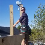 It would seem as though column notches can be on the same side in all bays except 1, due to the end wall trusses needing to be notched on the outside to be flush with outside building edge (which would make the end wall notches face in opposite directions). Is this correct? MATT in SPOKANE
  DEAR MICHELLE: Amanda (Hansen Pole Buildings’ financing wizardress) received a notification from you filling out our finance questionnaire; however, was waiting to get back to you until your quote was complete so we would have a better idea of how much you would need to borrow.
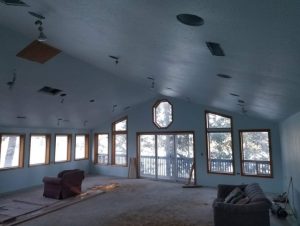 DEAR CHRIS: Saline County is located in Climate Zone 5A. As such conditioned buildings require R 60 attic insulation.
 DEAR MARK: Thank you for your kind words about our YouTube videos.
  DEAR POLE BARN GURU: Do you all have barns with living quarters? Not looking for a barndominium, per se, but a restroom with a shower and a living room in addition to 4 stalls and a tack room. we plan on staying there at first while we build the main house on the property, then use for guests or storage. SARAH in SARASOTA
 DEAR PETER: Unless your building has a very wide clearspan, or some huge dead loads (or perhaps a bonus room) a three ply truss seems strangely unusual. You might want to reach out to other possible truss manufacturers to see if you can get a two ply design. While I have seen three ply trusses notched in 4-1/2 inches approved by engineers, if indeed this is your final truss design solution, you should confirm connection adequacy by reaching out to your building’s Engineer of Record.
 DEAR POLE BARN GURU: Should the screws for exposed fastener metal panel roofing COMPLETELY penetrate the 1/2″ plywood decking/substrate? STEVE in WARREN
 DEAR TIM: Header beam (aka truss carrier) requirements can be determined by a Registered Professional Engineer and are based upon this formula:
 DEAR RICK: Code will not allow you to place batt insulation between your purlins unless you have at least an inch of continuous airflow above from eave to ridge. Impossible to do given orientation of roof purlins.
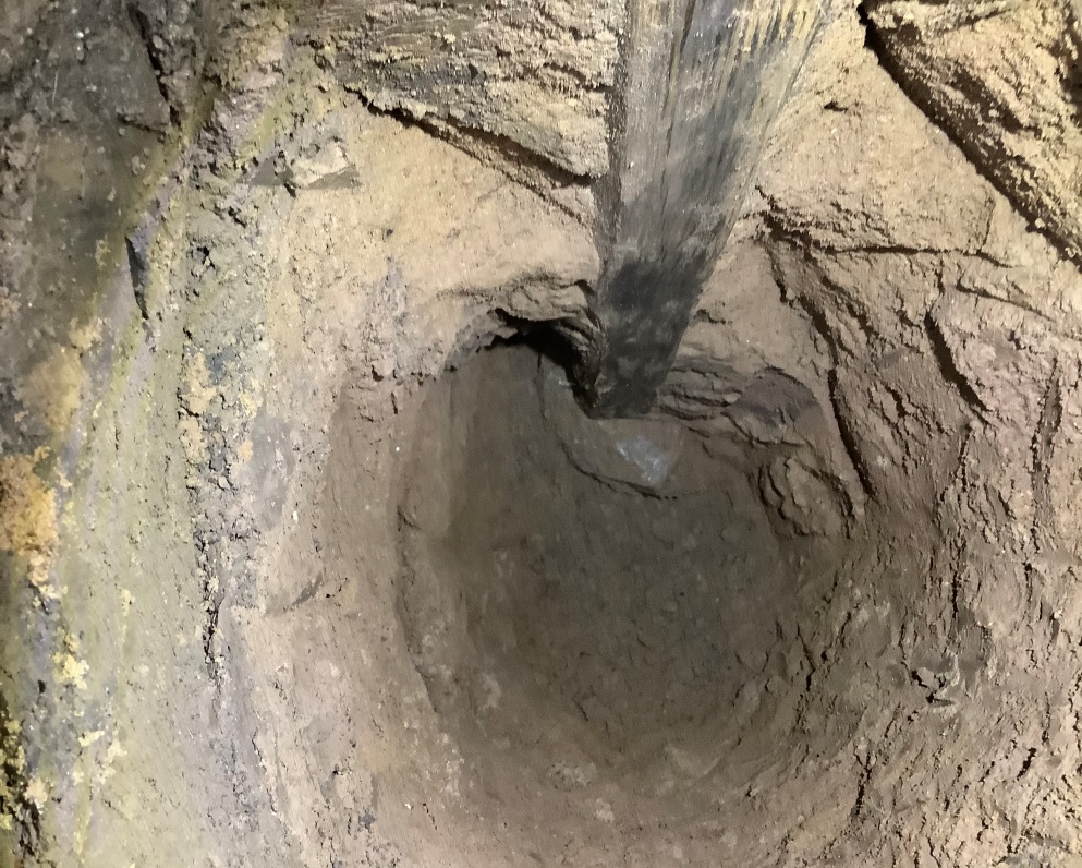
 Table 1C specifies an overall length of 5″ and 3″ of thread length. Allowable fastener shear is 1235# which by Footnote 4, “Allowable shear strength values apply only to shearing in the unthreaded shank portion of the fastener”. This would be fastener failure itself. This however is not our limiting value.
  DEAR POLE BARN GURU:
  DEAR POLE BARN GURU: Should I put plastic down under the stone floor in a steel building? BOB in WYALUSING
 LOAD (in psf – pounds per square foot) X (½ building width plus sidewall overhang in feet X 12”) X Distance spanned by beam squared (in feet)
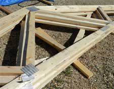 If this wasn’t a sexy use of technology, then I don’t know what would be.
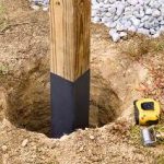 DEAR
DEAR DEAR TOM: You’ll want to make certain your proposed 20′ x 30′ area will be adequate for all of your needs. You may find increasing building footprint to say 24′ x 36′ to not be significantly more expensive of an investment, whilst providing 44% more space. With every building we provide being a custom design to best fit client needs, we can certainly provide exactly what you are looking for. A Hansen Pole Buildings’ Designer will be in contact with you shortly.