Tag Archives: dead load

How Far Can a 2×6 Purlin Span?

How Far Can a 2×6 Purlin Span?

Reader WILL in COMFORT writes:

How far can a 2×6 purlin on a 6:12 sloped roof span?”

The following describes 2×6 SYP #2 purlins spanning a 14′ bay, with an on-center spacing of 24″ (sf).

Purlins are recessed between rafters with their top edges flush with rafter top edges. Purlins are mounted to rafters with Simpson Strong-Tie LU-26 joist hangers at both ends.

Effective simple beam span length (le) will be taken as 165.

Applied loads

Dead load, D[

Dpurlin: dead load from weight of purlin itself
Dpurlin = purlin density × ((b × d × le) / (sf × l))
Purlin density found via NDS Supplement 2015 Section 3.1.3:
density = 62.4 × (G / (1 + (G × 0.009 × moisture content))) × (1 + (moisture content / 100))
moisture content = 19%
density = 62.4 × (0.55 / (1 + (0.55 × 0.009 × 0.19))) × (1 + (0.19 / 100))
density = 34.56 pcf
Dpurlin = 34.56 pcf × ( ( 1.5″ × 5.5″ × 165″ ) / ( 24″ × 168″ ) ) × 1/12 in/ft
Dpurlin = 0.966 psf

Roof designed for 29g corrugated steel
Dead load from weight of steel (Dsteel) based on values from the American Building Components catalogue:
Dsteel = 0.63 psf

D: dead load
D = Dpurlin + Dsteel
D = 0.966 psf psf + 0.63 psf psf
D = 1.596 psf

Project load to a vector acting perpendicular to the roof plane:
D = D × cos(Θ)
D = 1.596 psf × cos(0.464)
D = 1.428 psf

A conversion from psf to psi will be made for ease of calculation:
D = 1.428 psf × 1/144 psi/psf
D = 0.01 psi

Roof live load, Lr

L: roof live load
Lr = 18 psf

Project load to a vector acting perpendicular to the roof plane:
Lr = Lr × cos(Θ) × cos(Θ)
Lr = 18 psf × cos(0.464) × cos(0.464)
Lr = 14.4 psf

A conversion from psf to psi will be made for ease of calculation:
Lr = 14.4 psf × 1/144 psi/psf
Lr = 0.1 psi

Snow load, S

S: snow load
S = 13.267 psf

Project load to a vector acting perpendicular to the roof plane:
S = S × cos(Θ) × cos(Θ)
S = 13.267 psf × cos(0.464) × cos(0.464)
S = 10.614 psf

A conversion from psf to psi will be made for ease of calculation:
S = 10.614 psf × 1/144 psi/psf
S = 0.074 psi

Wind load, W

W: wind load
W = 9.6 psf

A conversion from psf to psi will be made for ease of calculation:
W = 9.6 psf × 1/144 psi/psf
W = 0.067 psi

Wind uplift load, Wu

Wu: wind uplift load
Wu = -11.763 psf

A conversion from psf to psi will be made for ease of calculation:
Wu = -11.763 psf × 1/144 psi/psf
Wu = -0.082 psi

Lr ≥ S, so roof live loads will dictate in load combinations.

Bending test (fb / Fb′ ≤ 1.0)

Fb: allowable bending pressure
Fb′ = Fb × CD × CM × Ct × CL × CF × Cfu × Ci × Cr
CL = 1
CM = 1 because purlins are protected from moisture by roof
Ct = 1 NDS 2.3.3
CF = 1 NDS Supplement
Ci = 1 NDS 4.3.8
Cr = 1 NDS 4.3.9

S: section modulus
S = (b × d2) / 6
S = (1.5″ × (5.5″)2) / 6
S = 7.563 in3

w: pounds force exerted per linear inch of beam length
M: maximum moment
fb: maximum bending stress

Load combinations:

  1. D

CD = 0.9
Cfu = 1
Fb′ = 1000 psi × 0.9 × 1 × 1 × 1 × 1 × 1 × 1 × 1
Fb′ = 900 psi

w = (D) × sf
w = 0.008 psi × 24″
w = 0.186 pli

M = (w × l2) / 8
M = ( 0.18559992381479 pli × (165″)2 ) / 8
M = 654.797 in-lbs

fb = M / S
fb = 654.797 in-lbs / 7.563 in3
fb = 86.585 psi

fb / Fb′ ≤ 1.0
86.585 psi / 900 psi ≤ 1.0
0.096 ≤ 1.0

  1. D + Lr

CD = 1.25
Cfu = 1
Fb′ = 1000 psi × 1.25 × 1 × 1 × 1 × 1 × 1 × 1 × 1
Fb′ = 1250 psi

w = (D + Lr) × sf
w = 0.108 psi × 24″
w = 2.586 pli

M = (w × l2) / 8
M = ( 2.5855999238148 pli × (165″)2 ) / 8
M = 9121.997 in-lbs

fb = M / S
fb = 9121.997 in-lbs / 7.563 in3
fb = 1206.214 psi

fb / Fb′ ≤ 1.0
1206.214 psi / 1250 psi ≤ 1.0
0.965 ≤ 1.0

  1. D + W

CD = 1.6
Cfu = 1
Fb′ = 1000 psi × 1.6 × 1 × 1 × 1 × 1 × 1 × 1 × 1
Fb′ = 1600 psi

w = (D + W) × sf
w = 0.074 psi × 24″
w = 1.786 pli

M = (w × l2) / 8
M = ( 1.7855999238148 pli × (165″)2 ) / 8
M = 6299.597 in-lbs

fb = M / S
fb = 6299.597 in-lbs / 7.563 in3
fb = 833.004 psi

fb / Fb′ ≤ 1.0
833.004 psi / 1600 psi ≤ 1.0
0.521 ≤ 1.0

  1. D + Wu

CD = 1.6
Cfu = 1
Fb′ = 1000 psi × 1.6 × 1 × 1 × 1 × 1 × 1 × 1 × 1
Fb′ = 1600 psi

w = (D + Wu) × sf
w = -0.074 psi × 24″
w = -1.775 pli

M = (w × l2) / 8
M = ( -1.7748379435325 pli × (165″)2 ) / 8
M = -6261.628 in-lbs

fb = M / S
fb = -6261.628 in-lbs / 7.563 in3
fb = -827.984 psi

fb / Fb′ ≤ 1.0
-827.984 psi / 1600 psi ≤ 1.0
-0.517 ≤ 1.0

  1. D + 0.75Lr + 0.75W

CD = 1.6
Cfu = 1
Fb′ = 1000 psi × 1.6 × 1 × 1 × 1 × 1 × 1 × 1 × 1
Fb′ = 1600 psi

w = (D + 0.75Lr + 0.75W) × sf
w = 0.133 psi × 24″
w = 3.186 pli

M = (w × l2) / 8
M = ( 3.1855999238148 pli × (165″)2 ) / 8
M = 11238.797 in-lbs

fb = M / S
fb = 11238.797 in-lbs / 7.563 in3
fb = 1486.122 psi

fb / Fb′ ≤ 1.0
1486.122 psi / 1600 psi ≤ 1.0
0.929 ≤ 1.0

  1. D + 0.75Lr + 0.75Wu

CD = 1.6
Cfu = 1
Fb′ = 1000 psi × 1.6 × 1 × 1 × 1 × 1 × 1 × 1 × 1
Fb′ = 1600 psi

w = (D + 0.75Lr + 0.75Wu) × sf
w = 0.021 psi × 24″
w = 0.515 pli

M = (w × l2) / 8
M = ( 0.51527152330431 pli × (165″)2 ) / 8
M = 1817.878 in-lbs

fb = M / S
fb = 1817.878 in-lbs / 7.563 in3
fb = 240.381 psi

fb / Fb′ ≤ 1.0
240.381 psi / 1600 psi ≤ 1.0
0.15 ≤ 1.0

Purlin stressed in bending to a maximum of 96.5%

Shear test (fv / Fv′ ≤ 1.0)

Fv: allowable shear pressure
Fv′ = Fv × CD × CM × Ct × Ci
CM = 1 because purlins are protected from moisture by roof
Ct = 1 NDS 2.3.3
Ci = 1 NDS 4.3.8
V: max shear force
fv: max shear stress

Load combinations:

  1. D

CD = 0.9
Fv‘ = 175 psi × 0.9 × 1 × 1 × 1
Fv‘ = 157.5 psi

V = w × (le – (2 × d)) / 2
V = 0.186 pli × ( 165″ – (2 × 5.5″) ) / 2
V = 14.57 lbs

fv = (3 × V) / (2 × b × d)
fv = (3 × 14.57 lbs) / ( 2 × 1.5″ × 5.5″ )
fv = 2.649 psi

fv / Fv′ ≤ 1.0
2.649 psi / 157.5 psi ≤ 1.0
0.017 ≤ 1.0

  1. D + Lr

CD = 1.25
Fv‘ = 175 psi × 1.25 × 1 × 1 × 1
Fv‘ = 218.75 psi

V = w × (le – (2 × d)) / 2
V = 2.586 pli × ( 165″ – (2 × 5.5″) ) / 2
V = 202.97 lbs

fv = (3 × V) / (2 × b × d)
fv = (3 × 202.97 lbs) / ( 2 × 1.5″ × 5.5″ )
fv = 36.904 psi

fv / Fv′ ≤ 1.0
36.904 psi / 218.75 psi ≤ 1.0
0.169 ≤ 1.0

  1. D + W

CD = 1.6
Fv‘ = 175 psi × 1.6 × 1 × 1 × 1
Fv‘ = 280 psi

V = w × (le – (2 × d)) / 2
V = 1.786 pli × ( 165″ – (2 × 5.5″) ) / 2
V = 140.17 lbs

fv = (3 × V) / (2 × b × d)
fv = (3 × 140.17 lbs) / ( 2 × 1.5″ × 5.5″ )
fv = 25.485 psi

fv / Fv′ ≤ 1.0
25.485 psi / 280 psi ≤ 1.0
0.091 ≤ 1.0

  1. D + Wu

CD = 1.6
Fv‘ = 175 psi × 1.6 × 1 × 1 × 1
Fv‘ = 280 psi

V = w × (le – (2 × d)) / 2
V = -1.775 pli × ( 165″ – (2 × 5.5″) ) / 2
V = -139.325 lbs

fv = (3 × V) / (2 × b × d)
fv = (3 × -139.325 lbs) / ( 2 × 1.5″ × 5.5″ )
fv = -25.332 psi

fv / Fv′ ≤ 1.0
-25.332 psi / 280 psi ≤ 1.0
-0.09 ≤ 1.0

  1. D + 0.75Lr + 0.75W

CD = 1.6
Fv‘ = 175 psi × 1.6 × 1 × 1 × 1
Fv‘ = 280 psi

V = w × (le – (2 × d)) / 2
V = 3.186 pli × ( 165″ – (2 × 5.5″) ) / 2
V = 250.07 lbs

fv = (3 × V) / (2 × b × d)
fv = (3 × 250.07 lbs) / ( 2 × 1.5″ × 5.5″ )
fv = 45.467 psi

fv / Fv′ ≤ 1.0
45.467 psi / 280 psi ≤ 1.0
0.162 ≤ 1.0

  1. D + 0.75Lr + 0.75Wu

CD = 1.6
Fv‘ = 175 psi × 1.6 × 1 × 1 × 1
Fv‘ = 280 psi

V = w × (le – (2 × d)) / 2
V = 0.515 pli × ( 165″ – (2 × 5.5″) ) / 2
V = 40.449 lbs

fv = (3 × V) / (2 × b × d)
fv = (3 × 40.449 lbs) / ( 2 × 1.5″ × 5.5″ )
fv = 7.354 psi

fv / Fv′ ≤ 1.0
7.354 psi / 280 psi ≤ 1.0
0.026 ≤ 1.0

Purlin stressed in shear to a maximum of 16.9%

Deflection test (Δmax / Δallow ≤ 1.0)

I: moment of inertia
I = b × d3 / 12 NDS 3.3.2
I = ( 1.5″ × (5.5″)3 ) / 12
I = 20.797 in4

E: modulus of elasticity
E′ = E × CD × CM × Ct × Ci
CM = 1 because purlins are protected from moisture by roof
Ct = 1 NDS 2.3.3
Ci = 1 NDS 4.3.8

Δallow: allowable deflection
Δmax: maximum deflection

Load combinations:

  1. D + Lr

CD = 1.25
E′ = 1400000 × 1.25 × 1 × 1 × 1
E′ = 1750000 psi

Per IBC 1604.3 footnote d, dead load may be taken as 0.5D.
w = ((0.5 × D) + Lr) × sf
w = ( (0.5 × 0.01 psi) + 0.1 psi ) × 24″
w = 0.104 pli

Δallow = l / 150 IBC 1604.3
Δallow = 165″ / 150
Δallow = 1.1″

Δmax = (5 × w × l4) / (384 × E′ × I)
Δmax = ( 5 × 2.493 pli × (165″)4 ) / ( 384 × 1750000 psi × 20.797 in4 )
Δmax = 0.661″

Δmax / Δallow ≤ 1.0
0.661″ / 1.1″ ≤ 1.0
0.601 ≤ 1.0

  1. D + W

CD = 1.6
E′ = 1400000 × 1.6 × 1 × 1 × 1
E′ = 2240000 psi

Δallow = l / 150 IBC 1604.3
Δallow = 165″ / 150
Δallow = 1.1″

Δmax = (5 × w × l4) / (384 × E′ × I)
Δmax = ( 5 × 1.786 pli × (165″)4 ) / ( 384 × 2240000 psi × 20.797 in4 )
Δmax = 0.37″

Δmax / Δallow ≤ 1.0
0.37″ / 1.1″ ≤ 1.0
0.336 ≤ 1.0

  1. D + Wu

CD = 1.6
E′ = 1400000 × 1.6 × 1 × 1 × 1
E′ = 2240000 psi

Δallow = l / 150 IBC 1604.3
Δallow = 165″ / 150
Δallow = 1.1″

Δmax = (5 × w × l4) / (384 × E′ × I)
Δmax = ( 5 × -1.775 pli × (165″)4 ) / ( 384 × 2240000 psi × 20.797 in4 )
Δmax = -0.368″

Δmax / Δallow ≤ 1.0
-0.368″ / 1.1″ ≤ 1.0
-0.334 ≤ 1.0

  1. D + 0.75Lr + 0.75W

CD = 1.6
E′ = 1400000 × 1.6 × 1 × 1 × 1
E′ = 2240000 psi

Δallow = l / 150 IBC 1604.3
Δallow = 165″ / 150
Δallow = 1.1″

Δmax = (5 × w × l4) / (384 × E′ × I)
Δmax = ( 5 × 3.186 pli × (165″)4 ) / ( 384 × 2240000 psi × 20.797 in4 )
Δmax = 0.66″

Δmax / Δallow ≤ 1.0
0.66″ / 1.1″ ≤ 1.0
0.6 ≤ 1.0

  1. D + 0.75Lr + 0.75Wu

CD = 1.6
E′ = 1400000 × 1.6 × 1 × 1 × 1
E′ = 2240000 psi

Δallow = l / 150 IBC 1604.3
Δallow = 165″ / 150
Δallow = 1.1″

Δmax = (5 × w × l4) / (384 × E′ × I)
Δmax = ( 5 × 0.515 pli × (165″)4 ) / ( 384 × 2240000 psi × 20.797 in4 )
Δmax = 0.107″

Δmax / Δallow ≤ 1.0
0.107″ / 1.1″ ≤ 1.0
0.097 ≤ 1.0

Purlin stressed in deflection to a maximum of 60.1%

Load Duration Factor for Wood

Load Duration Factor for Wood

Load Duration Factor, or LDF, is based on wood’s ability to recover after a reasonable load has been applied for a given time. Wood is a stiff material but it is not completely rigid. Wood will flex under load, and once load has been removed, wood member will rebound or spring back to its original shape (if load was not excessive or applied for too long). LDF is relevant in regular service load cases expected to act on a structure and member in consideration must resist without failure. LDF does not address loads overstressing a member to breakage point.

Some loads are expected to act on a structure for short time periods, such as wind and seismic loads whose duration would normally be measurable in seconds. Other loads, such as snow, might last at least three months, depending on geography. Dead loads are permanent and they are expected to act on a structure for its life. Load Duration Factors allow us to increase wood’s load carrying capacity based on how long a load is expected to act on a structure—shorter time period, higher allowed increase.

Load Duration Factors are applied to member capacity or resistance, not to loads on member. Only those capacities or resistances related to wood’s ability to recover from a load are subject to LDF adjustments, i.e. moment and shear. Bearing capacity is not adjusted for LDF for IBC (International Building Code). Instantaneous deflection is also not affected by LDF because we are measuring how far a member flexes, not for how long. There is a deflection analysis type called Creep Analysis, it checks long term deflection beyond instantaneous deflections due to heavy loads acting on a member for long time periods. Our software does not analyze this deflection type because North American building codes do not require creep analysis. 

Load Duration Factors are tightly integrated into load combinations used to load a member, i.e. if a load combination has both dead and wind loads then load duration factor for this load combination will be higher value defined by wind. Even though a load combination may have more permanent loads, by default load combination will apply shortest acting load’s LDF. Our software will run through all load combinations and their LDFs as required by building codes and will pick one producing highest stresses as critical load combination for a particular design check.

IBC allows engineers to choose what load duration factor (CD) can be applied with a given load. Table below shows LDF default values and ranges our software allows.

Default LDF Range Loading
CD = 0.90 Dead load only
CD = 1.00 0.90 – 1.00 Floor and Heavy Snow Load
CD = 1.15 1.00 – 1.15 Snow Load
CD = 1.25 1.00 – 1.25 Roof Load, Construction Load
CD = 1.60 1.00 – 1.60 Wind Load, Seismic Load

Notice our software defaults to the highest possible factor (liberal, but correct most times). For example, a structure for an area with heavy snow loads lasting in place for half a year, it would be reasonable to reduce your snow LDF to 1.00. Always consult your local building officials when in doubt.

Sharkskin Ultra

Sharkskin Ultra®

Sharkskin Ultra® is a high-performance roof underlayment for all steel roofing applications over solid decking (OSB – Oriented Strand Board or plywood).

https://sharkskinroof.com/sharkskin-products/sharkskin-ultra/

Construction professionals know how important a quality roof system is. This is why so much research, time and effort goes into specifying and installing right roofing products for every home and building.

Sharkskin Ultra® is the original patented synthetic roof underlayment. Designed to ensure quality roof installations are not short changed by inferior “old technology” asphalt felts, or cheap inferior commodity based synthetic roof underlayments. Sharkskin Ultra® is the heaviest, most robust, mechanically fastened polypropylene polymer based product commercially available. Its industry leading high-tensile strength provides the highest tested wind resistance and 12-UV rating available.

Sharkskin Ultra® has a unique patented design using multiple layers of blended polypropylene to achieve:

High tensile strength for durable secondary moisture protection (face it – if water somehow gets through a properly installed steel roofing application, you really do not want it going any further). Plus, if your primary roofing is blown off, it provides a secure secondary water barrier.

High traction non-slip surface for excellent grip and safe walking, even in wet or dusty conditions. Obviously, always use caution and fall protective gear especially in wet weather and windy conditions. There are few things more terrifying than butterflies in one’s stomach as you slide down a roof towards eave edge. In 1988 my Dad was killed in a construction fall off a roof, so I am very sensitive to this one.

Weighing only 50 pounds per 10 square roll (48” x 250’), its light weight makes for faster installations and reduces dead loads on roof systems.

12 months UV resistance, providing long term protection under protracted roofing installations.

ICC-ES, Miami Dade and Florida Building Code approved.

Performs in all temperatures from -40 to 280 degrees F. (Fahrenheit), making it perfect for steel roof installations.

Light grey surface is cooler for installers to work with and walk over than black asphalt impregnated felt. Can be easily marked with a crayon and holds chalk line markings. AS it will not scar or melt, there is no sticky mess like with asphalt impregnated felt (tar paper).

Installs with 3/8” roofing nails, no cap nails required and provides long term nail seal-ability per ICC-ES AC48.

Comes with a manufacturer’s 50-year warranty.

Considering steel roofing over a solid sheathed roof deck? If so, Sharkskin Ultra® might be a design solution to be considered.

Why Self Engineering is Risky

Reader MICHAEL in EAGLE POINT writes:

“I want to span 18 feet on a shed roof with any pitch necessary should I nail two 2x 6 rafters together and place this in the center and use 9 foot 2×6 purlins. The shed will be 18 X 18. Do I need to nail two 2×6 together for the two outside rafters?

All spans are clear span no center post The high side of shed is up against an existing building the low side will be new post and beam or posts with the rafters bolted to the post

This is a shed with only two walls. The existing high side as explained and the new post and beam side as the low side The two other sides will be open to drive under.

I plan on three or four posts on the low side depending on whether I use beams post to post underneath the rafters Or Bolt the rafters to either side of the post and eliminate the beams.

Since I’m using 2 x 6 purlins between the rafters I wondered if I could span the 18 foot length using two 2 by sixes (nailed together )For rafters. Since I’m using purlins I thought I could only have the rafters at each end and one in the center keeping in mind it is only a metal roof.”

Mike the Pole Barn Guru responds:
This sort of armchair ‘engineering’ is far too typical of what I read in social media groups.  When designs such as what is proposed are utilized, and buildings fail, folks are quick to point fingers as pole buildings being responsible, rather than lack of proper engineering design being our true culprit.

Please confirm this with your Registered Professional Engineer who will be sealing your building plans. Most of Oregon (your part included) has a minimum roof live load of 25 psf (pounds per square foot).  For sake of discussion, we will use 3 columns spaced nine foot on center along low and high sides and a five psf dead load (just in case someone decides to add plywood or OSB under a reroof some day).

Moment force = (25 + 5) psf x (9′ distance to next rafter / 2 [1/2 distance to next rafter] x 12″) x 18’^2 [ span of rafter] / ( 8 x 1.15 [Cd = duration of load for wood]) = 57,052.17 in-lbs

57,052.17 / (2 x 31.6406 [Section Modulus of a 2×12]) = 901.57 Fb [fiberstress in bending] required

2×12 #2 DougFir has a Fb of 900, so given bearing width at each end would most likely be approved by your engineer.

For rafters I would recommend a 2 ply 2×12 #2 DougFir on each end, and at center use two rafters on each side of the column. Connection at ends must be capable of withstanding 1215# so a single bolt will be nowhere near adequate (again, your engineer will properly design and detail this connection). Your thought of nailing two 2×6 together would be woefully inadequate (and would be over 300% over stressed probably failing during construction).

Hiring a Registered Professional Engineer is not an expense, it is an investment.

End Truss Overhang Dilemma

Reader ANDY in HAYDEN has an end overhang challenge. He writes:

“Hello Mr Guru. I’m building a 30x40x12 post frame with 18″ eaves. My trusses builder doesn’t build drop cord ag trusses for my gable over hangs. I was advised to lower the gable truss on the corner post to allow room for my on edge 2×8 purlinings  to extend over the top. I have a 16×10 garage door planned for below that over hang, will this method work. Can ladders be used?. I would appreciate your help sir. I know if I had the money I could have ordered one of your kits. Trust me I wish but I was born with a spork in my mouth and I’m just chipping away monthly on my project. Thank you for any help.”


Mike the Pole Barn Guru responds:

Most of our clients were not born with any sort of silver or plastic ware in their mouths – me either. While my brother and I did not realize it growing up, we were probably upper lower class in family income, but we were happy, our parents worked hard and we learned well from them. I have joked, “We were so poor our mother used to spray paint our feet black and lace up our toes”. It was not quite as bad – but Mother did go without socks for some time so we could have clothes.


Moving forward – there are advantages to investing in an engineered complete building kit package and not try to piecemeal. I have written about piecemealing before https://www.hansenpolebuildings.com/2014/03/diy-pole-building/. Ordering trusses can, as you have just found out, be far more difficult than it seems. https://www.hansenpolebuildings.com/2020/02/things-roof-truss-manufacturers-should-ask/

Financing is highly affordable, with some amazingly low interest rates and most suppliers have options available to delay some deliveries until you are more prepared for them.

Before you get carried away with an overhang, look at your engineered truss drawings. Guessing your building has a pair of trusses every 10 feet and a single truss on each end, it will need to be designed to account overhang weight plus any other dead loads and snow loads. To accomplish this, your end trusses should be designed with either one truss at five foot (plus a notation stating they can support an 18 inch end overhang), or have a spacing of 6’6″. If neither of these has occurred you need to contact your truss supplier for an engineered repair. It may be cheaper to use a double truss on one end (notching into corner and end columns, and purchase a correct new truss for the opposite end.

In any case, before there is any structural deviation from your engineered plans YOU MUST CALL YOUR ENGINEER. My suggestions are merely my opinion and are not to be construed as my supplying or practicing engineering. If you deviate from your engineered plans in any fashion, all liability for structural integrity falls directly upon you.

Measurements below are using this for a measure of eave height https://www.hansenpolebuildings.com/2015/02/eave-height-2/

Having taken care of loading issues in some fashion, you can lower your end trusses by 7-5/8″ to adjust for vertical component at a 4/12 slope (other slopes change this hold down dimension). This should put the bottom of your end trusses at 10′ 10-1/2″ for a 2×6 top chord truss (again at 4/12) or 10′ 8-3/4″ for a 2×8 top chord.

Bottom of your overhead door header should be at 10′ 5″ above grade (bottom of splash plank). This leaves 3-3/4″ only (2×8 Top chord) or 5-1/2″ with a 2×6 top chord for your overhead door header. Keep in mind, below an end truss this header carries absolutely no roof load. It exists merely to be a place for a row of screws or nails (non-steel sidings) and to be a place to attach an overhead door spring block to. If you were erecting a Hansen Pole Building, your end truss would be notched into your corner and endwall columns 1-1/2″ This allows for a 2×8 overhead door header to be installed above the top overhead door jamb and lapping onto end truss bottom chord 3-1/2″ (1-3/4″ with 2×6 top chord). Balance of end truss chords would have a 2×4 Std&btr nailed across to provide backing for siding and act as a stiffener resisting lateral loads and buckling.

Another advantage of a complete package is it should come with a detailed step-by-step assembly manual. At Hansen Pole Buildings this means 500 pages. 

Your engineer can verify if you can for 2×6 top chord truss place a 2×6 as a header between top jamb and truss, or move top jamb up 1/4″ and use a 2×4.

Ladder framing nailed or screwed to the face of end truss to create end overhangs is probably not structurally adequate and it could very well sag, if not fall off.

Best wishes.

An Oops from a Competitor’s Architect Part Two- Lateral Load

As the Architect Turns

In our previous episode, we left Dan tied to railroad tracks in front of a speeding train….

Well close, we left Dan with a post frame building designed by an architect, with some serious structural connection problems.  Now I am a guy who watches Science Channel’s “Engineering Catastrophes”. I would just as soon we do not view Dan’s barndominium as one of them.

Moving forward from our last article:

It will shred LVL and/or column – wood is your weak link

You need to calculate the area being carried by one beam end beam – on an 8′ beam with 18′ joists you would have 8’/2 X 18’/2 = 36 sft (square feet).

Minimum floor live load (other than for bedrooms) is 40 psf (pounds per square foot) live load and you should figure 10 psf dead load for a total of 50 psf.

36 sft X 50 psf = 1800 pounds at each end of 8′ in this example.

Dan writes:

So I have the table you referenced and I get the load calcs but what I am trying to figure out is how you got to the 7 ledgerlocks per post figure. What is the math to get from that table and the 3600 lbs per eight foot section to the amount of ledgerloks?

And since we have gone down this rabbit hole, should I start to get paranoid that one of my 3 truss carriers is affixed with 60d nails and that I need to do a lateral load calc on that in order to make sure it is properly connected?  My guess is that this design was based on shear as well…

Ugh  this is what goes on in the mind of a DIY builder who is a data analyst by day.”

Mike the Pole Barn Guru responds:

Let’s do a run-down of information from ESR-1078 for 5″ Ledgerlock Fasteners (for those playing along at home Google ESR-1078).

Table 1C specifies an overall length of 5″ and 3″ of thread length. Allowable fastener shear is 1235# which by Footnote 4, “Allowable shear strength values apply only to shearing in the unthreaded shank portion of the fastener”. This would be fastener failure itself. This however is not our limiting value.

Table 2 references withdrawal design values – LVL is not likely to be sucked away from column by wind, so not applicable.

Table 3 is head pull-through design values – these values limit numbers derived from Table 2, again not applicable.

Table 4 is for Lateral Design Values in single shear. It lists a 5″ ledgerlock with a minimum of 1-1/2″ side member thickness and 3-1/2″ minimum main member thickness. As your LVL is 1-3/4″ thick, lateral design values will need to be adjusted downward by X 0.929 to account for a lesser length into column. Most glu-laminated post frame building columns are Southern Yellow Pine (SYP).  SYP has a specific gravity of 0.55, so a RDP could possibly calculate out values approximately 10% greater.

In your case, load is perpendicular to side member, parallel to column grain. Using Z perpendicular to grain and Sg of 0.5, adjusted for lesser depth into main member would give a value of 280# X 0.929 or 260.12#. Assuming an RDP could gain 10% for greater Specific Gravity, value per Ledgerlock would still be only 286.13#

With an 1800# load / 286.13# = 6.29 fasteners.

You might want to invest in having a qualified engineer review your plans for adequacy. Yes, there will be a price however you may have recourse against original provider and/or their architect in the event of significant structural deficiencies.

Had our Building Designer not given Dan bad advice, all of this could have easily been avoided. Hansen Pole Buildings, in conjunction with our third-party engineers has developed a sophisticated proprietary software program called Instant Pricing™. Not only will this system provide required investment for a myriad of design parameters in real time, it also does a complete structural analysis of every component and connection – assuring situations such as Dan has, will not arise.

Dead Load, Sliding Barn Doors, and Truss Spacing

This weeks PBG discusses a bottom chord dead load, installing sliding barn doors, and truss spacing.

DEAR POLE BARN GURU: Ok, just to make sure I understand that 10lb psf dead load rating would cover the bottom chords supporting ducts either resting on or suspended from them inside the conditioned space? My thinking is if the vents are within the conditioned space I would need minimal insulation to prevent surface condensation. ROB in ANNAPOLIS

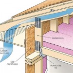
DEAR ROB: 10 psf dead load is primarily to cover weight of ceiling gypsum wallboard. Your relatively light duct could be placed anywhere within roof system without adverse effects. A down side to placing duct work within a conditioned attic – effectively insulating roof slope plane and endwall triangles. For practical purposes this can only be achieved with closed cell spray foam. While being highly effective as an insulator, about R-7 per inch of thickness, it comes with a price tag not for those who are faint of pocketbook – usually around a dollar per square foot per inch of thickness. If you go this route, you need to eliminate venting eaves and ridge.

DEAR POLE BARN GURU: Good morning,

Figure 27-5

I need to get some pricing on a (2) 6’-0” wide x 8’-0” high sliding barn style doors for an agricultural building in Ware county Ga.


I have never purchased, or installed a door like this, so I was hoping you could help me get started.


Thanks, DAVID in KENNESAW

DEAR DAVID: Thank you very much for your interest. Hansen Pole Buildings only provides doors along with an investment in a complete post frame building kit package, due to high incidence of damage when shipped independently. We do have installation instructions available online: https://www.hansenpolebuildings.com/2016/07/build-sliding-door/.


DEAR POLE BARN GURU: What would the truss spacing need to be in our area that has a 40lb snow load? RODNEY in REPUBLIC

joist hangers
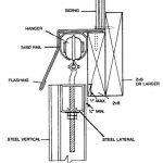
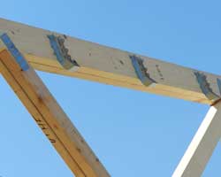
RODNEY: In most instances a true double truss (not two single trusses spaced apart by blocking) will be most cost effective, as well as adequate to carry applied loads (along with properly sized roof purlins). However, depending upon a myriad of other factors such as eave height, truss span, roof slope and building length some other spacing may result in cost savings.

This will be just one reason I recommend consulting with a post frame building kit supplier who has sophisticated design software able to do a near instantaneous analysis of multiple possibilities. This supplier should also be able to provide site specific plans for your building, sealed by a registered design professional.


What Size Truss Carriers?

What Size Truss Carriers?

It seems every day I am asked to do structural design of post frame buildings – for free. Today’s request comes from BOB in ARKDALE who writes:

“Yesterday I asked a question about a double header and single trusses being spaced every 4 feet with 8 foot spacing on posts. I don’t use the internet much but a reply to my son’s email address would be great. The question was what is a proper double header? We thought one underneath the other off entered or sandwiched off enter.”


Bob’s earlier request was somehow spun off into an internet abyss, as it did not make it successfully to us.

nailing trusses
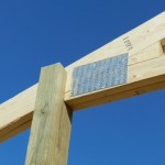
In my humble opinion, an ideal design solution eliminates need for a header (aka truss carrier) entirely, by having trusses bear directly upon columns. Why would this be ideal? Trusses (in my ideal dream world) are placed into a field cut notch in each column. This transmits all roof loads directly onto posts, without reliance upon beams typically scabbed onto each side. This eliminates trusses being driven to earth in a catastrophic snowfall event.

Back to your question – size and number of required members for your headers, as well as their orientation) should be clearly denoted upon plans provided by RDP (Registered Design Professional – architect or engineer) who produced them. Headers and their connections need to be able to withstand all imposed loads – live (snow), dead (weight of headers themselves along with trusses, purlins, insulation, roof sheathing (if used), roofing, any ceiling, lighting, etc.), as well as wind loads (uplift being a factor). These headers must be adequate to support one-half of clearspan width of your building, plus any overhangs beyond sidewall.

All of this takes an involved series of calculations best performed by an experienced RDP. If you somehow do not have one involved in your project – go hire one right now. This small investment into correct structural design becomes inconsequential compared to pain of building loss should it fail, damaging or destroying valuables your building was meant to protect, as well as injuring or killing yourself or your loved ones who may be inside when the roof caves in.