Tag Archives: truss plates

Will I Need to Use Double Trusses?

Will I Need to Use Double Trusses?

Reader DALE in TOMPKINSVILLE writes:

“On an open front 5 bay tool shed, roof length 60 feet, width 40 foot, height of 10 foot, 12foot, trusses on 6×6 columns, 12/4 pitch located in southern Kentucky zone 6 will I need to double the trusses?”

Need and want are two different things. In all likelihood, single trusses will support your climactic loads. Double trusses do have some distinct advantages however.

ASABE (American Society of Agricultural and Biological Engineers) published ANSI/ASABE S618 “Post Frame Building System Nomenclature” in December 2010. For those who are unfamiliar ANSI stands for American National Standards Institute (www.ansi.org). ANSI is a private non-profit organization overseeing development of voluntary consensus standards for United States products, services, systems and personnel.

In ANSI/ASABE S618, a Metal plated connected wood truss would be described as, “A truss composed of wood members joined with metal connector plates (also known as truss plates). Metal connector plates (MCP) are light-gauge, toothed steel plates. The most common type of light wood truss.” Ganged wood trusses are defined as, “A truss designed to be installed as an assembly of two or more individual light wood trusses fastened together to act as one.”

nailing trussesFor Hansen Pole Buildings, any time we are using a “real” double (more specifically ganged) truss system, we specify top chords to be a minimum of 2×6, regardless of loads. I say “real” because placing a single truss along each side of a column is not a double truss. They are two single trusses, acting independently from each other. A true double truss system, such as used by Hansen Pole Buildings, features trusses physically attached face-to-face by means of mechanical connectors (e.g. nails, bolts, etc.). This allows for two members to actually load share, reducing probabilities of one weak single truss failing and pulling a roof system down with it.

True ganged trusses, due to their load sharing capabilities, often are able to utilize smaller steel connector plate, smaller or lesser dimension lumber for chords and/or webs, and require far less lateral bracing. Often utilization of two-ply ganged trusses results in a less expensive overall structural design solution, when all factors are taken into consideration.

Three sided buildings also pose their own unique set of structurally challenges, please read more here: https://www.hansenpolebuildings.com/2014/03/three-sided-building/

Having to Wait for Prefabricated Metal Plate Connected Wood Trusses?

Having to Wait For Prefabricated Metal Plate Connected Wood Trusses

nailing trussesLately I have read social media posts of people having to wait for as long as six months to get prefabricated metal plate connected wood trusses (MPCWT).

We received this notification from one of our major MPCWT providers:

“Our truss plate supplier has informed us that a worldwide steel shortage is severely impacting product availability,  shipping lead times and material costs. To review the letter from MiTek that explains the truss plate environment in detail (Letter is below in this article). You are receiving this communication to inform you of the latest supply chain shortage.

We anticipate the steel shortage will last through at least the next couple of quarters, if not longer, as demand for steel increases with economic improvement and the auto industry works through their backlog of orders caused by the semiconductor chip shortage.

The housing construction supply chain continues to be strained by material shortages, strong demand, transportation issues, and reluctance of manufacturers and mills to bring on more supply. We understand the challenges our builders are facing and we are urgently working to mitigate supply issues in any way we can. 

Unfortunately, despite our best efforts we anticipate the truss plate shortage will have some effect on our truss production capacity, lead times and design. Steps we will be taking to mitigate the steel shortage include diligently working to optimize available plate inventory when designing, prioritizing our truss production for existing customers, suspending DIY and one-off truss projects, and exploring other sourcing options.”

Here, at Hansen Pole Buildings, we spend hundreds of thousands of dollars a month on MPCWT, so we do have a certain degree of priority over those who are DIYing it.

Below is Mitek’s letter:

April 29, 2021 

Dear Valued MiTek Customer, 

By now you have most likely spoken with your MiTek Sales Representing who would have explained the process MiTek has implemented to address the severe demand/supply imbalance the steel industry is experiencing. This letter is to give you clear visibility to the situation and to our approach to work through this with you. 

The Current Situation 

Over the last two weeks disruptions in the global steel industry have continued to deepen, creating worst supply challenges in memory. Although there are varied and diverse aspects to this situation, here are just few of contributing factors:

Many industries, including steel producers, radically reduced inventory levels Q2 and Q3 of 2020 

Massive unexpected post-lockdown surges in demand from nearly all steel consuming industries and primary building materials (lumber, aluminum, roofing, etc.) 

The new automotive annual build rate is almost 17mm units, despite the widely reported microchip shortages. 

Residential construction is booming, with the SAAR for housing starts in March reaching 1.74mm units 

The merger of Cleveland Cliffs and ArcelorMittal USA further concentrated supply and pricing power in the hands of a few US companies who have publicly stated their intentions to maintain prices at elevated levels. 

Global demand and the excessive 232 tariffs have limited import opportunities 

Rail, truck, and ocean freight logistics are extremely challenging. 

Impact 

These factors have combined to create the perfect storm. In early 2021 steel producers severely curtailed tonnage allocations – and lead times jumped from the typical 8 weeks to 4 to 5 months. At the same time, on-time delivery performance from the mills, hardly stellar in a normal market, has plummeted. By way of example, MiTek has received just 55% of committed steel deliveries from our supplier base through April. Once the late steel begins arriving (anticipated in mid to late May) it will quickly be applied against the growing backlog of connector plate orders stemming from incredible demand levels (see below). 

And of course, as with all primary materials, each month steel prices continue to rocket past historical records. The AMM Index for Hot Dipped Galvanized exceeded $85/cwt in mid-April, or nearly 90% higher than October 2020. 

Housing Market Demand 

On the demand side, much higher than anticipated starts, coupled with the start-up of additional planned component manufacturing capacity, has caused order entry and shipping rates from our CM partners to far exceed original projections. Annualized, shipments to our CM customers in the January through April 2021 time frame are very close to the annualized 2005 volume when 2.05mm units were started. Demand is intense, and order entry rates over the past two weeks suggest the pace may in fact be quickening. 

Our Approach 

As indicated in previous communications, when steel allocations tightened and lead times jumped out in January and early February, MiTek committed to forward purchases of substantial steel volumes for May, June, July and August at elevated prices. Assuming delivery of these orders takes place as near as possible to the original promise dates, we are hopeful the need to extend connector lead times and tightly control order entry may begin to abate towards the end of the summer. Our steel supply partners, both domestic and international, tell us they are “catching up” against huge backlogs, however recent delivery performance warrants a level of caution. 

Given these factors, we are now at a juncture where we must put in place a more formal order management process to ensure we can support as much of your product needs as possible. 

Effective April 27 we are implementing an order control process, with established monthly order entry targets, by customer, equivalent to, on average, approximately13-15% more than average monthly connector shipments in 2020. New connector orders will be entered with a four-week lead time. Specific customer order entry targets will be communicated by your MiTek Sales Representative. Lead times and target levels may need to be further adjusted – to more closely mirror rapidly changing demand/supply conditions. 

Current orders on hand, and new orders placed, in excess of monthly target levels will be committed for delivery in the following month and counted against that next month’s target level. 

We understand this situation is disruptive for our CM partners. Implementing these unprecedented measures was a last resort, and only came after many hours of analysis and consideration of the factors mentioned earlier. These steps are necessary in order to ensure a level of continuity of supply. 

MiTek’s commitment to our CM partners remains unwavering and we will continue to provide the highest level of transparency around the deepening supply chain disruptions. Through clear, frequent, and timely communication we will navigate the challenge together. 

Should you have any further questions please feel free to reach out to your MiTek sales representative. 

Thank you as always for your business. 

Best regards, 

Thomas J. Valvo President, Homebuilding Solutions

Hansen Pole Buildings regards our commitment to our clients and to providing “The Ultimate Post-Frame Building Experience” seriously. In my next article, I will address steps we are taking to ensure our clients receive their buildings and truss systems as expediently as possible and without sacrifice of structural integrity.

Long-Span Truss Installation Guidance for Post-Frame

Long-Span Truss Installation Guidance for Post-Frame
Originally published by: Construction Magazine Network(link is external) — January 18, 2021
The following article was produced and published by the source linked to above, who is solely responsible for its content. Hansen Pole Buildings, LLC is publishing this story to raise awareness of information publicly available online and does not verify the accuracy of the author’s claims. As a consequence, Hansen Pole Buildings, LLC cannot vouch for the validity of any facts, claims or opinions made in the article.
Editor’s Note: The article below is the first in a ten-part Structural Building Components Association series on long-span truss installation guidance specific to the post-frame industry, all of which will be published in Frame Building News(link is external).
By Sean Shields, With Contributions by Jim Vogt, P.E.

If you’ve installed long-span wood roof trusses long enough, you’ve likely experienced the “spaghetti” effect, where the truss members bend or buckle out of plane and make the truss very difficult to handle. It’s one thing if it happens while you’re hoisting a single truss into place. It’s quite another when a group of trusses are already installed and they all start to flex out of plane together!

Why does it happen? Is it because they were designed wrong? Is it because they were manufactured incorrectly? Is it because they’re “cheap” or made with inferior raw materials? These are common questions and accusations, but they aren’t accurate. This article, and the series it kicks off, will look at how trusses are designed to function in the structural framework of a building, and why it’s so essential to handle these structural components correctly on the job site to avoid the “spaghetti” effect and other issues.

How Trusses Work
Since their invention in 1952, metal plate-connected wood roof trusses have proven themselves to be the most economical and material-efficient structural framing solution for many of today’s buildings. Their superior performance is due to the triangulation of the chords and webs, and their subsequent ability to efficiently transfer loads applied to the top or bottom chords of a truss to its bearing locations.

Further, the ability of the metal connector plates to efficiently connect the chord and web members together, and transfer the member forces across the joints, are what has driven the market to replace traditional stick-framing methods with trusses in almost 80% of all wood roof structures in North America.

It’s important to note, however, that trusses are designed to only support loads applied within a specific, typically vertical, plane. Trusses are narrow in relation to their depth and span and thus require lateral support. Without this lateral support, the truss, or a portion of its members, will buckle out-of-plane (i.e. lateral bending) under far less load than the truss is designed to resist when applied in an unintended manner. This lateral bending increases as the truss span lengthens, which explains why it is more difficult to keep longer span trusses in plane throughout the installation process. Once a truss is subject to loads (even gravity loads) outside of those planes it is specifically designed to support, you have potential to experience the “spaghetti” effect.

How Trusses Are Made
From a manufacturing standpoint, the most efficient way to produce a roof truss is in the horizontal position. If you haven’t been inside a truss manufacturing facility before, touring one would be well worth your time. You’ll witness how the individual wood members are cut and assembled on large tables, the plates are then tacked in place, and then a large press embeds the plates evenly. After the truss is assembled, it’s typically put on a conveyor that takes it out into the yard where each truss is stacked and bundled with trusses of the same or similar size for a particular job. These bundles are then picked up by forklift and placed on the trailer of a truck to be transported to the job site.

All of this is to emphasize that while the trusses are typically manufactured in a horizontal orientation, they are minimally handled as individual trusses in this orientation. Why? Again, because metal plate-connected wood trusses have significantly reduced strength while oriented flatwise and lateral bending can easily cause damage. Banding the trusses together provides greater rigidity to the bundle of trusses and minimizes out-of-plane bending.

Handling Trusses on the Job Site
The effects of banding groups of trusses is beneficial for the manufacturer, but it doesn’t help the installer who is tasked with handling individual trusses during installation. What can be done to minimize lateral bending on individual trusses in the field? Here are three best practices:
First, talk with whomever is delivering the trusses to the job site. The next article in this series will address site preparation and best practices for placement and storage, but it’s important to note that one of the best ways to minimize lateral bending is to limit the amount each truss is handled. Ensuring the trusses are delivered on the job site and off-loaded to a location optimal for installation requires planning and good communication. Ideally, this happens before the truck shows up on site.

Second, make sure the equipment you are using to lift the trusses into place is adequate for the job. An upcoming article will specifically cover best practices for different kinds of equipment. In this context, the key element is ensuring that the lifting capacity and reach of the equipment far exceeds the weight of the trusses you are installing and distance the machinery extends to place each truss.

When picking up individual trusses, maneuver them in the vertical, or in-plane, position as much as possible, taking special care to minimize lateral bending. When lifting a truss off the ground, it’s best to have more than one pick point so the weight is distributed between two or more points, as opposed to being concentrated in one point at or near the peak. Longer span trusses require multiple pick points as well as “strongbacking” of adequate length and stiffness to keep the truss from deflecting out of plane.

Third, adequately brace the first truss installed to ground bracing and all subsequent trusses to it and each other to ensure the trusses remain in-plane throughout the installation process.

Consequences of Lateral Bending
The primary purpose of roof trusses are to provide structural resistance to anticipated loads over the life of the structure. This may seem basic, but it’s vital to understand the implications of that statement. Again, all of the loads a truss is designed to resist are within the plane of the truss. The truss is not designed to resist or withstand deflection out-of-plane. When this occurs, significant damage can occur to one or more joints in a truss.

Sometimes the damage is evident during installation. A web member or chord may crack or break. A metal connector plate may begin to pull out of the wood or even come off. Installers can spot this kind of damage without great difficulty and an appropriate repair can be provided and implemented in the field. In some cases, however, the damage caused by lateral bending may not be immediately evident. This can lead to unexpected performance issues later on in the life of the building. At that point, repairs or replacement can cause serious headaches for the building owner.

The Bottom Line
To the greatest extent possible, avoid lateral bending of trusses during the installation process. This can cause significant damage to a truss, sometimes in ways that are not readily apparent. To minimize the potential for lateral bending, make sure the trusses are delivered to a location on the job site that reduces necessary handling, only use equipment that allows you to move individual trusses in a plumb and upright position and enable multiple pick points, and adequately brace trusses during installation to ensure they remain in-plane.

What Fails First in a Fire? Part II

What Fails First in a Fire- the Truss Lumber or the Steel Truss Plates? Part II

If you didn’t read my blog yesterday, you will think me out in left field until you do.  Take a few extra minutes and go back and read Part I. You will be glad you did!

Continuing from yesterday’s blog on hay catching fire, and causing a pole barn to burn:

What do you do if you suspect your hay is heating?

A simple probe inserted into the haystack can accurately monitor temperature. You can make a probe from a 10-foot piece of pipe or electrical tubing. Sharpen the pipe or screw a pointed dowel to one end, then drill several 1/4-inch diameter holes in the tube just above the dowel. Drive the probe into the hay stack and lower a thermometer on a string into the probe. The thermometer should be left for 10 minutes in several areas of the stack to ensure an accurate reading.

Watch for the following temperatures:

150 degrees F is the beginning of the danger zone. After this point, check temperature daily.

160 degrees F is dangerous. Measure temperature every four hours and inspect the stack.

At 175 degrees F, call the fire department. Meanwhile, wet hay down and remove it from the barn or dismantle the stack away from buildings and other dry hay.

At 185 degrees F hot spots and pockets may be expected. Flames will likely develop when heating hay comes in contact with the air.

212 degrees F is critical. Temperature rises rapidly above this point. Hay will almost certainly ignite.

Take precautions. Pockets may have already burned out under the hay surface.

Before entering a barn, place long planks on top of the hay. Do not attempt to walk on the hay mass itself. Always tie a rope around your waist and have a second person on the other end in a safe location to pull you out should the surface of the hay collapse into a fire pocket.

Hay treated with preservatives may produce hydrogen cyanide gas at 240 degrees F, so extreme caution should be taken when fighting a hay fire if hay has been treated with such preservatives. Hay treated with preservatives containing ethoxyquin and BHT (butylated hydroxytoluene) produce hydrogen cyanide gas at around 240 degrees. This gas is deadly. Additives containing primarily propionic acid to not produce hydrogen cyanide during a fire.

In the past, farmers sprinkled salt on wet hay as it was stacked to prevent spoilage, but salt does not prevent spontaneous combustion. Dry ice, liquid nitrogen or carbon dioxide gas pumped into the hay can prevent combustion by eliminating the oxygen from the hay mass.

Hay fires from spontaneous combustion occur infrequently in the arid western U.S., but can be a hazard for new hay or old stacks.

Good storage practices will avoid spontaneous combustion and ensure higher quality hay.

As the pressed steel connector plates do not appear to be the weak link of the truss system, if the investment of time and effort is going to be put into what to do when there is a fire, rather than preventing one to begin with, then the use of fire retardant treated lumber for the trusses might prove to be a better place to spend one’s money.

What Fails First in a Fire?

What Fails First in a Fire- the Truss Lumber or the Steel Truss Plates? Part I

We have a client who also happens to be an engineer. He is planning upon a rather goodly sized (64 feet wide by 96 feet long by 22 foot eave) hay storage building and had some rather interesting concerns.

Here is his first one:

nailing trussesHe is concerned about collapse in a fire, which can happen with hay not properly dried.  He has either read or heard pressed metal truss connector plates are one of the first things to fail, in the event of a fire, causing the trusses to fail and bring the building down.


I did enjoy the response from Hansen Pole Buildings Managing Partner Eric, The whole fire question just seems odd to me. So he is worried about the building not collapsing in the case of a fire but basically knows in the event of a hay fire the building will be worthless regardless? I mean when you have a building in a hay barn it is toast no matter what it is made out of. Get your marshmallows out and watch the blaze because there isn’t any stopping it.

If the worry is more about fire I would think a sprinkler system would be the only worthwhile investment here.”

I took it a little bit further:

From the testing results I have read, it appears the pressed steel connector plates actually help to protect the wood behind and immediately adjacent to the plate. For the curious, here is the link to the test results: https://www.fire.nist.gov/bfrlpubs/fire07/PDF/f07004.pdf.

The best bet is to prevent hay fires from occurring.

Oddly enough, wet hay is more likely to lead to a spontaneous combustion fire than dry hay. If hay is put into a barn or stack when it has more than about 22 percent moisture, not only does the hay lose forage quality, but it has an increased risk of spontaneous combustion.

High moisture hay stacks can have chemical reactions which build heat. Hay insulates, so the larger the haystack, the less cooling there is to offset the heat.

When the internal temperature of hay rises above 130 degrees F, a chemical reaction begins to produce flammable gas which can ignite if the temperature goes high enough.

Hay fires generally occur within six weeks of baling. Heating occurs in all hay above 15 percent moisture, but generally it peaks at 125 to130 degrees F, within three to seven days, with minimal risk of combustion or forage quality losses. Temperature within a stack then declines to safe levels in the next 15 to 60 days, depending on bale and stack density, ambient temperature and humidity, and rainfall absorbed by the hay.

To avoid hay fires, small, rectangular bales should not exceed 18 to 22 percent moisture, and large round or rectangular bales should not exceed 16 to 18 percent moisture for safe storage. If the moisture content exceeds these limits, simply do not stack the bales inside of your new building – allow them to first dry in the field.

In addition, you should check your hay regularly. If you detect a slight caramel odor or a distinct musty smell, chances are your hay is heating. At this point, checking the moisture is too late, and you’ll need to keep monitoring the hay’s temperature.

What do you do if you suspect your hay is heating?

Come back tomorrow and I will impart sage advice!


Roof Truss Repair

Roof Truss Repair

A builder writes:

Roof Truss RepairThe previous owner of a pole building I’m working on cut out several internal webs from three consecutive roof trusses to create storage space in the attic. There’s no sign that this has caused any structural problems so far, but I’d like to replace the missing members and fasten them with plywood gusset plates and construction adhesive. Is this feasible, and does this sort of seat-of-the-pants field repair expose me to any legal liability?”

An “arm chair engineered field repair” will expose the builder to liability, should the repair ever fail. Field truss repairs can be made, and they probably would resemble something like what has been suggested. Ideally, an engineer affiliated with the truss manufacturer which produced the trusses would design a suitable repair. But if the truss manufacturer is unknown or no longer in business, the builder should engage an engineer who would both sign off on the design, and inspect and approve the work afterward.

The best place to start is with the manufacturer of the connector plates used on the original trusses. Take pictures of the condition, along with close-up pictures of the connector plates on the trusses and send them to any truss manufacturer. They should be able to point the builder in the right direction.

A typical truss repair might call for a combination of dimensional lumber and plywood gussets “scabbed” beside the remaining web members to make up for the lost members. The repair design should include material dimensions for added members, plus a detailed fastener schedule showing the size, number, and placement of fasteners.

Regardless of the specific design details, under no circumstances should the builder take responsibility for the repair. The fact there have been no structural problems yet doesn’t mean there won’t be some down the road. This may not be enough in the event of high winds, a record snowfall, or a decision by the building owners to move all their old college textbooks into the attic.

Richard Feeley of Feeley Mediation & Business Law, a Marietta, Georgia law firm which provides legal counsel to remodeling companies, confirms a contractor should not attempt a truss repair without engineering support. “If you touch it, you own it,” he warns. A contractor who has not partnered with an engineer to make sure the truss repair meets code and complies with structural requirements is indeed liable, and the risk could be great. Liability could include not just property damage but personal injury if the truss system fails and someone gets hurt.

There can also be licensing implications. If, for example, the job is “permitted” and a building inspector finds after the fact an adjustment which required an engineered design was made.

Feeley points out another legal dimension contractors need to address as well: Be sure you cover the issue in your contract. “You need a change-order policy that covers unforeseen circumstances,” Feeley says. “If you find something that no one expected, you want to be sure you get paid for the work it’ll take to repair it.”

My best advice – don’t field modify any prefabricated roof truss, without adequate engineering.

Truss Connectors: What to Use on Damaged Trusses

As noted yesterday, damaged trusses warrant a repair design by a professional…a licensed engineer.  This is not something for “guesswork” or scabbing on a bunch of lumber.  First the forces of where damage occurred need to be analyzed, and then only an engineer with solid experience in repairing damages should be engaged to elicit the repair design using appropriate truss connectors.

Fastener selection can often prove to be a challenging exercise, due to the wide variety of truss connectors available. The metal plates used in the manufacture of wood trusses have excellent grip due to the numerous teeth embedded into the lumber. When calculating the quantities of other mechanical fasteners required to repair a damaged plate, it is often surprising to see how much larger the connection areas become.

Generally, the nail is the most widely used fastener for wood construction. Nails are commonly referred to by penny-weight. Unfortunately, this designation does not have clearly defined dimensions. There may be four or more different nails commonly referred to by a single penny-weight. For example, a 10 penny (10d) nail could refer to a sinker, common, box, cooler or pneumatic (gun) nail, all of which are slightly different. To eliminate confusion, it is important to note nail length and diameter.

Wood screws are another option. Wood screws can have higher values than nails, but often require pilot holes to prevent splitting. Note many general purpose screws, such as deck screws and drywall screws, may share a common gauge number with a heavier wood screw, but are not considered structural due to the lower grade steel used in their manufacture and should be avoided for truss repairs. Recently, specialty screws have become available, resulting in superior performance in relation to standard screws. These screws are manufactured by United Steel Product, Simpson Strong-tie, and Fasten-Master, to name a few.

Machine bolts are generally used where high forces are involved. Truss connectors in wood trusses rarely benefit from high strength bolts, making them unnecessary. Carriage bolts are not recommended; the lack of a washer and solid bearing on the head of the bolt results in poor performance in relation to machine bolts. Lag screws may be used, but are of limited capacity due to the relatively thin (1-1/2-inch) thickness of the truss members. The lack of penetration limits their lateral strength significantly.

The use of adhesives for truss repairs raises considerable debate among engineers. The quality of some adhesives today allow for bonding wood with greater strength than the wood itself, resulting in much smaller connections. However, the conditions under which many truss repairs are performed can compromise the glue bond. For example, freezing temperatures, surface dirt, and unsupervised labor make the capacity of the glued joints difficult, if not impossible, to judge.

Mechanical fasteners can be counted to verify conformance with the repair specification. Unfortunately, once the glue is applied and covered, it cannot be seen without destroying the repair. Therefore, adhesive use is best left for controlled environments, such as factories and jobs where the responsible engineer can observe the application of the adhesives. If an adhesive is to be used, the curing time must be considered. In many instances, a truss must be repaired in place. Once a repair is completed, temporary supports are often removed and construction materials are placed on the truss immediately. This practice does not allow proper time for the adhesive to cure. One solution to this problem is to provide mechanical fasteners, designed to support the construction loads, allowing the adhesive the required time to gain sufficient strength before the full design load is applied to the truss.

One other school of thought is to specify the adhesive, but not to consider it in the calculations. This is most often done when repairing floor trusses. The mechanical fasteners transfer the forces and the adhesive provides insurance against squeaks. If the adhesive is omitted, the repair is still valid. If it is used, it only adds strength and stiffness to the repair.

A common practice used by many engineers to reduce the connection size is to “clinch” the nails used with gussets. In order to properly clinch nails, a gusset is placed on each face of a single ply truss. The gusset must be clamped or held in place securely during the nailing procedure. Nails are driven through the front gusset, through the truss, and through the gusset on the back face. The nails must then be bent over flat against the surface of the back gusset.  Please bear in mind clinching must be performed properly. Unfortunately, many repairs specifying clinched nails are performed incorrectly at the jobsite.

Due to the lack of code provisions governing truss repairs, engineering judgment becomes critical in the determination of what is acceptable. While the design capacities of various materials are available to aid an engineer’s calculations, there are times when repairs tend to bring the art of engineering to a level almost equal to the science.  Need a truss repair?  Call an engineer experienced in designing repairs for damaged trusses.  I always have, and always will.  Like concrete finishing, there are just some things best left to the experts.

Metal Connector Plates Have Teeth

Metal connector plates are used to connect wood truss members and are considered the most important invention in the light frame wood construction industry. This is due to their versatility, cost effectiveness and ease of installation. Typically composed of galvanized steel they are mainly manufactured using one of three metal thicknesses: 20, 18 and 16 gauges. The galvanization means the steel is coated with a zinc alloy for corrosion resistance. Stainless steel is also used to manufacture metal connector plates since plates are used in highly corrosive environments.

The interior pieces of a truss are webs and the continuous outside ones are the chords. Top and bottom chords typically directly carry the loads and transfer those loads to adjacent joints (the confluence of webs with the chords). The truss members can be of different sizes, grades and/or species of lumber. When constructing trusses, the members have to be in the same plane for the metal plates to connect them.

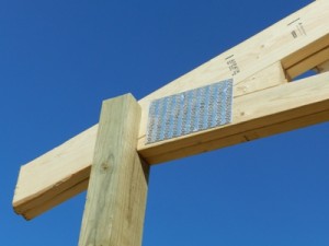
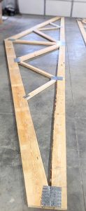
As shown in the picture metal truss plates have integral tooth slots. Each tooth has a particular shape, size and twist design depending on the plate manufacturer. These characteristics affect the load carrying capacity of the plate. Plates with teeth on one face are placed on both faces of a truss joint and are pressed with hydraulic or roller presses to embed the teeth into different web and chord members. Once the plate connects the web and chord members, it resists the forces coming from them. All plates on a truss joint are designed to withstand forces due to tension, compression, shear, and moment.

To ensure the plates can resist the forces coming from the truss members, each plate manufacturer tests them in tension and shear at different angles. A plate’s load carrying capabilities will differ at different angles. Tension and shear values of plates are also related to the metal strength used for plates. Plates are also tested for lateral resistance or gripping, which is directly related to the lumber strength. The stronger the lumber is, the higher the lateral resistance value will be. Each manufacturer publishes the design values of their truss plates.

Just as metal connector plates to join wood truss members created a burgeoning prefabricated roof truss industry, the affordability of wide span wood trusses has revolutionized the pole building industry. This advent has allowed for clearspans of 80 and even 100 feet to become practical using wooden pole barn design.