Chances are good if you have to ask a structural design question, then you are in over your head.
Reader LARRY in DITTMER writes:
“Can you 2 by 4 flat on an 8 foot span Truss”
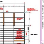
A few years ago, one of my neighbors bought a pole building kit from someone other than Hansen Pole Buildings. It was for a garage and sidewall columns and single roof trusses were placed every eight feet. Now I am relatively certain this building’s roof purlins were supposed to be 2×8 on edge between trusses – however for some obscure reason, they got installed flat wise! I am unsure as to how they were even able to get roofing installed without falling through.
 This is just one of many reasons why post frame buildings should be designed by a Registered Professional Engineer.
When it comes to designing whether a roof purlin can achieve a given span, it takes a lot of calculations – both for live or snow loads, as well as wind loads. In high wind areas, wind will fail purlins (or their connections) rather than snow! I have condensed calculations down to just bending and deflection and will use minimum snow loads in this example:
ROOF PURLIN DESIGN – Main Building (Balanced snow load)
Assumptions:
Roof slope = 4:12 (18.435° roof angle)
Trusses spaced 8-ft. o.c.
Purlin span = 8-ft.
Purlin spacing = 24 in.
Purlin size 2″ x 4″ #2 Southern Pine
Roof steel dead load = 0.63 psf steel American Building Components catalogue
Roof lumber dead load = 0.587 psf
Total purlin dead load = 1.217 psf
Check for gravity loads
Bending Stresses
Fb: allowable bending pressure
Fb‘ = Fb * CD * CM * Ct * CL * CF * Cfu * Ci * Cr
CD: load duration factor
CD = 1.15 NDS 2.3.2
CM: wet service factor
CM = 1 because purlins are protected from moisture by roof
Ct: temperature factor
Ct = 1 NDS 2.3.3
CL: beam stability factor
CL = 1 NDS 4.4.1
CF: size factor
CF = 1 NDS Supplement table 4B
Cfu: flat use factor
Cfu = 1.1 NDS Supplement table 4B
Ci: incising factor
Ci = 1 NDS 4.3.8
Cr: repetitive member factor
Cr = 1.15 NDS 4.3.9
Fb = 1100 psi NDS Supplement Table 4B
Fb‘ = 1100 psi * 1.15 * 1 * 1 * 1 * 1 * 1.1 * 1 * 1.15
Fb‘ = 1600 psi
fb: bending stress from snow/dead loads
fb = (purlin_dead_load + S) * spacing / 12 * cos(θ) / 12 * (sf * 12 – 3)2 / 8 * 6 / b / d2 * cos(θ)
S = 21.217 psf using the appropriate load calculated above
fb = 21.217 psf * 24″ / 12 in./ft. * cos(18.435) / 12 in./ft. * (8′ * 12 in./ft.)2 / 8 * 6 / 3.5″ / 1.5″2 * cos(18.435)
fb = 2961.59 psi > 1600 psi; stressed to 185.1%
Deflection
Δallow: allowable deflection
Δallow = l / 180 IBC table 1604.3
l = 96″
Δallow = 96″ / 180
Δallow = 0.533″
Δmax: maximum deflection
Δmax = S * spacing * cos(θ * π / 180) * (sf * 12)4 / 185 / E / I from http://www.awc.org/pdf/DA6-BeamFormulas.pdf p.18
E: Modulus of Elasticity
E = 1400000 psi NDS Supplement
I: moment of inertia
I = b * d3 / 12
I = 3.5″ * 1.5″3 / 12
I = 0.984375 in.4
Δmax = 21.217 psf / 144 psi/psf * 24″ * cos(18.435° * 3.14159 / 180) * (8′ * 12 in./ft.)4 / 185 / 1400000 psi / 0.984375 in.4
Δmax = 1.118″ > 0.533″; 209.68% overstressed in deflection
These calculations are based upon purlins every 24 inches on center. If you were to reduce spacing to say 11 inches on center then flatwise 2×4 #2 Southern Pine with a 20 psf roof snow load would be adequate.
If you were able to somehow acquire 2850f Machine Stress Rated 2×4 with a E value of 2300000 psi (very high grade material used by some truss manufacturers) spacing could be 18 inches on center.
Again – remember these equations are just for checking for bending due to a minimal snow load, wind conditions may dictate. Please consult with a Registered Professional Engineer for actual designs.


