While Alaska is America’s last great frontier, it doesn’t mean when we go North, we throw proper structural design out of a window.
Reader CRAIG in WILLOW has more challenges going on than he has dreamed. He writes:
“Hello,
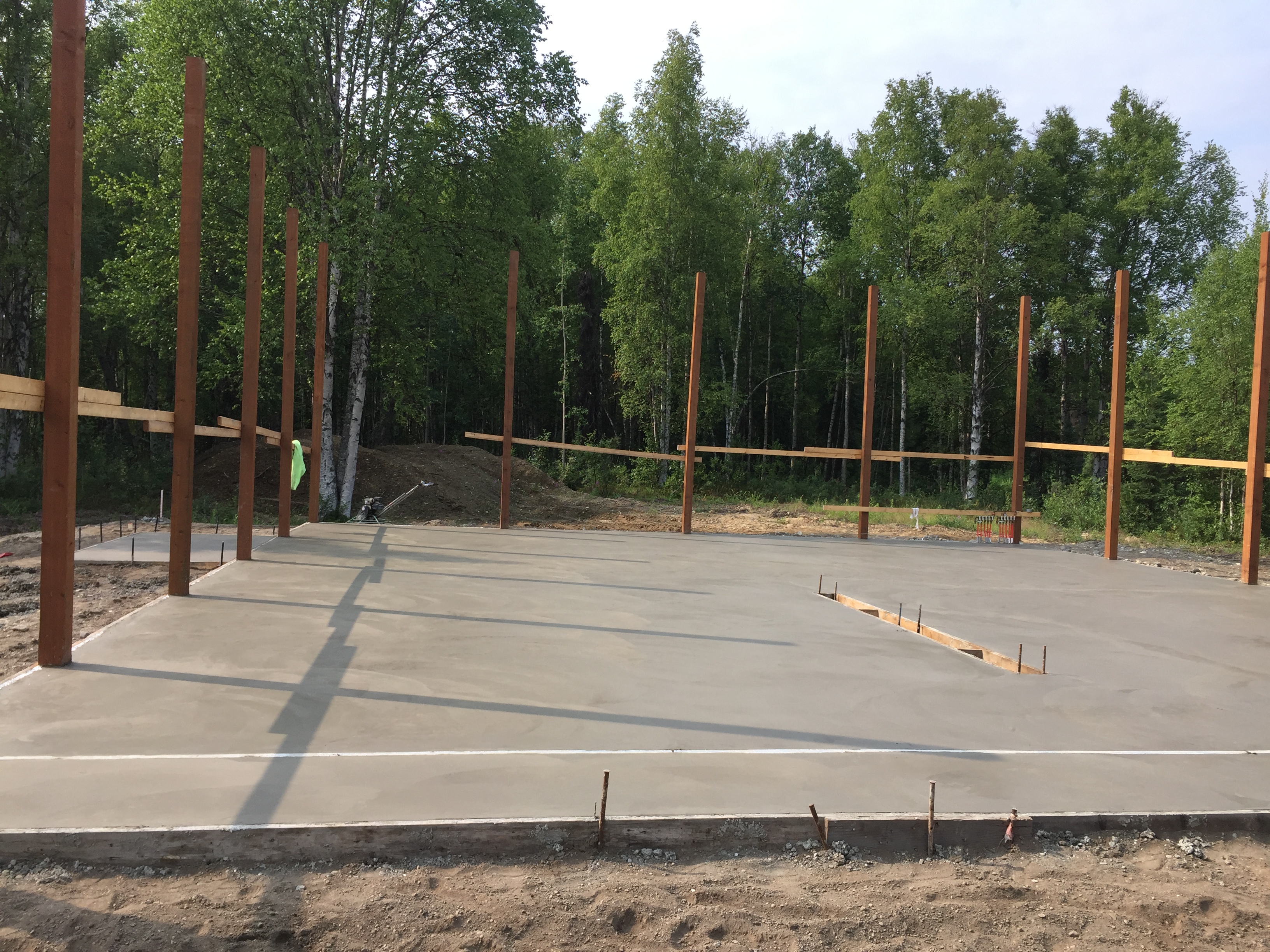
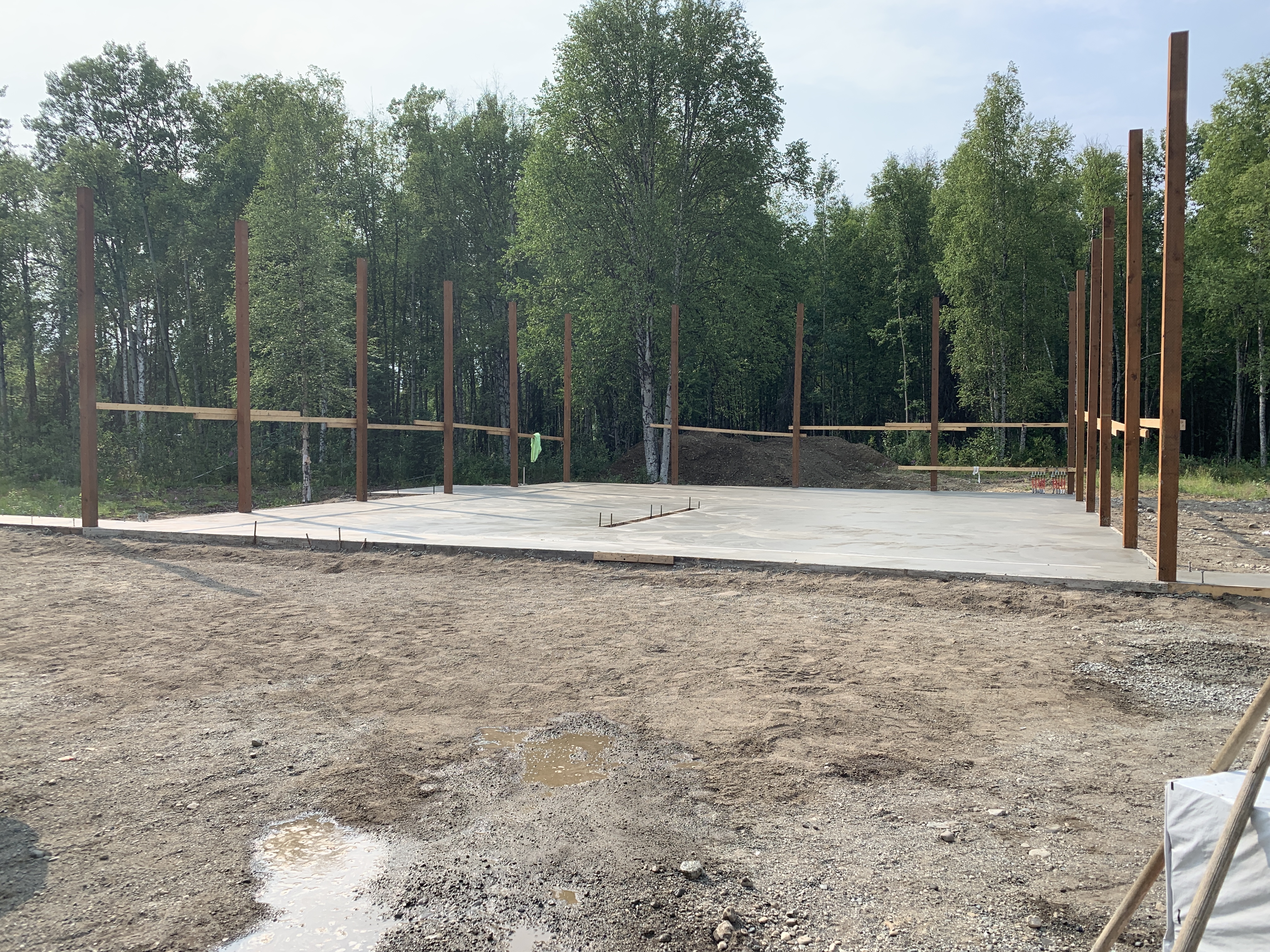
I’m building a 42Wx50D pole barn. I have 6×6 columns spaced 10’ apart on more than adequate footings. Slab on grade 5-6inches thick (poor final grading ) with 6” mesh and pens tubing. Willow has a snow load of 90:10:10. With a 4:12 pitch, truss companies up here are recommending a set of two two-ply trusses for a total of 24 trusses. 2’ overhang.
My problem is figuring out how to support the load between the trusses. They won’t give me a recommendation. I was planning on using 2×6 between top chords spaced every 2’. These would be oriented vertically and installed with joist hangers. I don’t think they’d be strong enough. The top chords on the trusses are called out at 2×6 so it’d be difficult to hang a larger member on them.
If I can’t make this plan work should I frame in between the columns and build a stick frame wall to set normal trusses on every 2 feet? What about laying some size beam across the tops of the columns and then setting trusses at 2’ centers? I’m dead in the water and want if anything to have overbuilt. Can you help? Thanks.”
Here is my response:
You have a plethora of challenges going on. This is why I always, always, always (did I mention always?) tell clients to ONLY build post frame (pole barn) buildings from engineer sealed plans produced specifically for their building at their site. It is not too late to get one involved and it will be money well spent.
Challenge #1 It is highly doubtful 6×6 columns you have placed along your building sidewall are going to be adequate to carry combined wind and snow loads. An engineer can design a repair – probably involving adding 2x lumber to one or both columns sides.
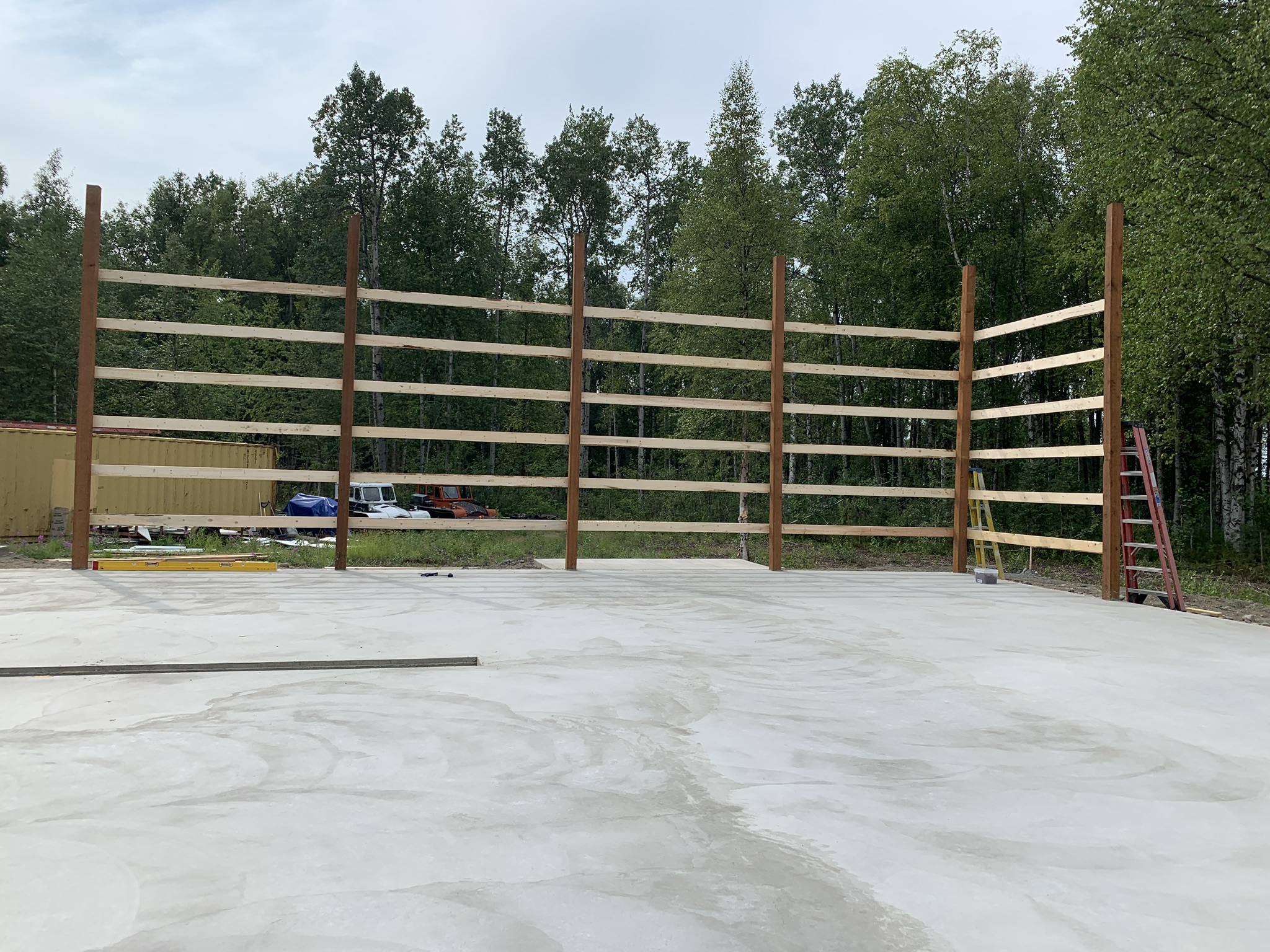
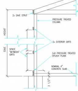
Challenge #2 Your wall girts placed on column faces “barn style” will not meet Code requirements – they will probably fail in bending and absolutely will not be adequate for deflection. https://www.hansenpolebuildings.com/2012/03/girts/
Again – an engineer can design a repair and there are several choices. You could remove them and turn them flat like book shelves between columns – you would need to add material for blocking at girt ends. https://www.hansenpolebuildings.com/2018/09/making-framing-work-with-bookshelf-girts/ Or, more girts could be added to your wall. Or, a strongback (2×4 or 2×6) could be added to your barnstyle girts to form an “L” or a “T”. My personal preference would be a bookshelf design, as it creates an insulation cavity.
Now – on to your trusses and roof purlins.
Your snow load is actually 90 psf (pounds per square foot). 10 and 10 are dead loads – you may not need ones these large. If you are using light gauge steel roofing over purlins top chord dead load can be as low as 3.3. Steel over sheathing 5. Shingled roof 7. If using steel roofing, make sure it is capable of supporting this snow load over a two foot span. If using sheathing, 7/16″ OSB or 15/32″ CDX plywood will not span two feet with a 90 psf snow load. Second 10 is bottom chord dead load. It is adequate to support the weight of ceiling joists, two layers of 5/8″ Type X drywall and blown in insulation. For a single layer of sheetrock and minimal lighting five psf is probably adequate. No ceiling – 1 psf. Important – make sure truss people are using 1.00 for DOL (Duration of Load) for snow. With your snow load, chances are snow is going to sit upon your building’s roof for a significant time period. Again, an engineer can determine what loading is adequate for your situation.
Trusses – how about placing three of them every ten feet? They can be notched into your columns from one side so you have full bearing – when two trusses are placed each side of a column, they are not acting together to load share.
Your roof purlin dimension can be larger than truss top chords – just utilize larger purlin hangers and balance of purlin can hang below top chord of truss. An engineer can confirm adequacy of hanger nails to support imposed snow and wind loads. Given your load conditions, your engineer should be looking to use something like 2×8 #2 purlins every 12 inches or 2×10 #2 purlins every 19.2 inches. You would not want to go to 2×10 unless truss top chords are at least 2×8.
You could stick frame between columns to support trusses every two feet. Any stud walls over 10′ tall do need to be designed by a Registered Design Professional (architect or engineer) as they would be outside of Building Code parameters. Your slab edges would also need to be thickened in order to support added weight. A beam could be placed from column to column to support trusses, you are probably looking at something around a 3-1/2″ x 14″ 2800f LVL.
If you are considering insulating an attic space, be sure to order raised heel trusses. They are usually no more expensive and they afford full insulation depth from wall-to-wall. https://www.hansenpolebuildings.com/2012/07/raised-heel-trusses/
With all of this said – go hire yourself a competent Registered Professional Engineer today to resolve your challenges. Otherwise you are placing yourself and your building contents at peril.
 I have to admit, Dan spoke with a Hansen Pole Buildings’ Designer who gave him bad advice – he recommended Dan go with a stick framed building! I would typically grill our Building Designer under high intensity lamps as to what was going through his head, however I cannot as for perhaps obvious reasons he has left us to seek other opportunities (I can put things so diplomatically when I try).


