Stud Walls Between Post-Frame Columns for Alternative Sidings?
Reader JAKE brings up an interesting question:
“Hello! I was looking at the blog for a question I had about wall girts for post frame buildings… I was wondering that if a form of siding is installed on the building other than sheet metal, needing wall sheathing, would it be structurally sound to frame 2×6 walls between your 12’ apart posts and not have wall girts? Just attaching the wall sheathing to the posts and 2×6 walls in between? Thank you!”
 Mike the Pole Barn Guru says:
Before we get to your structural question, a few words. 6×6 columns are notorious for having dimensional variability. I have seen them run as much as 3/4″ over dimension. An over 5-1/2 inch dimension would mean your columns are going to project either inside or outside of your stick framed interior wall.
Now we get into structural soundness.
My concern is how to adequately transfer loads from the top of the stud wall into columns.
Walls lie within two wind zones. Zone 5 is within 10% of least building footprint dimension, with a minimum of four feet. It applies to any secondary member with over 50% of its length within this zone. Provided your building is 60 feet or less in length and width and bays are 12 foot, it would not be applicable for your case.
Wind pressure is derived from wind speed “V”. For an Exposure B (protected from wind in all four directions) site, here are applicable loads in psf (pounds per square foot) for secondary components and cladding members (with mean roof height less than or equal to 15 feet) and a fully enclosed building:
MPH PSF (ASD – Allowable Stress Design)
95 10.527
100 11.664
105 12.86
110 14.114
115 15.426
120 16.797
125 18.226
130 19.713
135 21.258
140 22.862
All of these loads are negative, meaning your wall is trying to be sucked out of your building.
Arbitrarily picking 110 mph and a 10 foot wall height (if this is for a residence, or accessory building to a residence, then wall heights are limited to 11’7″ by IRC – International Residential Code Section R301.3):
Total load on a 12′ section of wall (by length) would be: 12′ x 10′ tall x 14.114 psf = 1693.68#. One half of this load is transferred to ground through bottom plate, and one half of remainder must be transferred through top plates to column or 423.42#.
When not nailed into end grain (through a plate into end of stud would be end grain and value is reduced x 0.67; toe-nailing reduces value x 0.83) a 10d common nail (3″ long x 0.148″ diameter) nail has a laterally loaded strength value of 102.022# with Hem-Fir or SPF lumber.
How to attach the wall section to the column is your challenge.
In order to nail through end stud into columns, connection at top of stud (nail driven through top plate) would take 423.42# / (102.022# x 0.67) = 6.19 nails. Probably unrealistic to expect to drive 7 nails into top of a single 2×6 stud.
How about toe-nailing plates to column? 423.42# / (102.022# x 0.83) = 5 nails. While ugly, this might be doable.
Ultimately, connection of top plates to columns would probably be cleanest by use of a Simpson Strongtie strap such an LSTA12.
For our example I have picked a fairly low design wind speed, so higher wind speeds will increase loads and make connections even more difficult. As building mean eave height increases beyond 15 feet, applied loads will increase. In order to meet enclosed building requirements – plan upon use of wind load rated doors (other criteria also apply to meet enclosed requirements), else applied loads may increase. Don’t have a protected site? Exposure C places a load approximately 20% greater than Exposure B on your building.
In summary, while what you propose might work, it should be checked by whatever engineer is placing his or her stamp on your building plans.

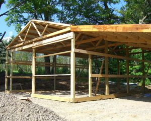
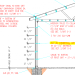 Rather than evenly spacing non-commercial bookshelf girts between splash plank and eave, we now have standardized spacing to fall so measures are evenly divisible into eight (8) feet. Examples are 32”, 24”, 19.2”, 16” all of which are keyed to markings on tape measures. With ends of girts solid blocked to columns, there really should be no need to measure anyhow (other than to cut blocks). Blocks can be cut, in quantity, speedily with a chop saw.
 DEAR JOSEPH: I will read between lines and guess you have built stud walls between building columns. If this is your situation then you will need to have horizontal girts added in order to attach wall steel vertically. You should refer to your engineered building plans for size, spacing and attachment of these girts, as your engineer is most likely counting on your steel skin to provide needed wall diaphragm strength.
 DEAR DAN: Well you have lots of possibilities. Given what you have provided, I would be inclined to cut roughly four feet from your high side (making your cut back another eight to 10 feet from your building) and then fill on low side, with a retaining wall eight to 10 feet beyond your building. This way you can slope grade away from building in both directions. Walls will be far enough away from building to not affect it. If you have clay in your soil, make sure to remove at least top 18-24 inches where building will be located and replace it with good, properly compacted fill.
 DEAR POLE BARN GURU:
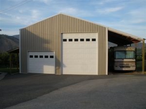 “I have plans to build a 52x48x14 this spring. The idea is 52×48 roofline 4/12 pitch. Under that roof is a 16×48 open side for rv parking and then 36×48 enclosed with concrete floor. My original thoughts are to 2×6 stick frame the wall separating the open area from the enclosed area after the pad is poured (any suggestions). 16×12 insulated door and a 4’ man door on the front gable end and a 3’ man door to get in from under the open area towards the rear.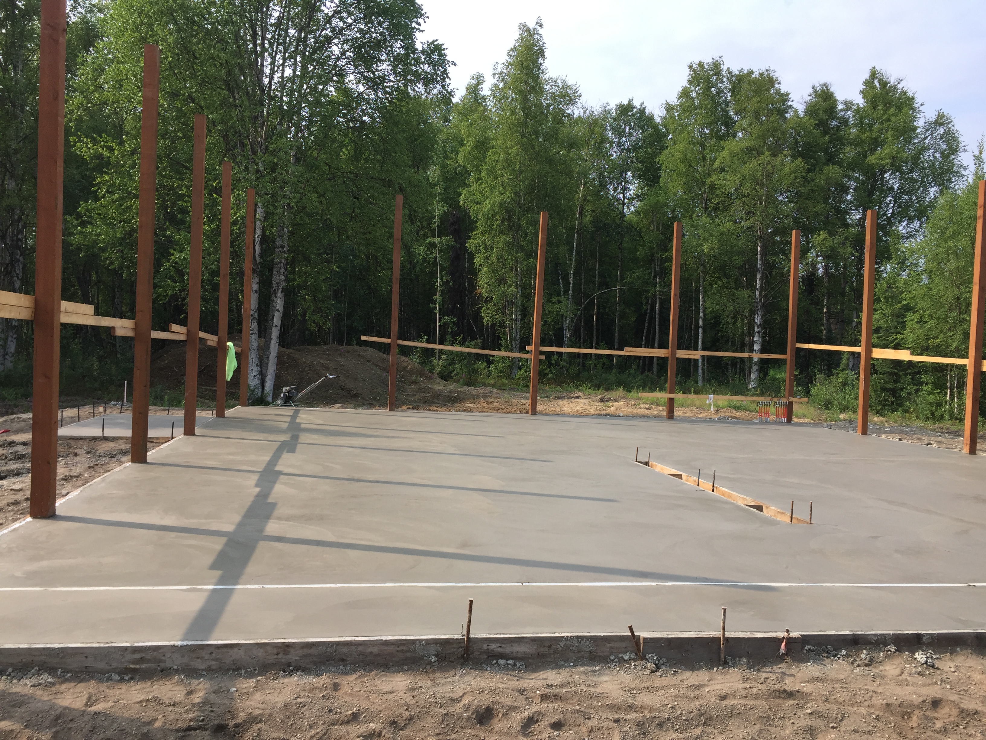
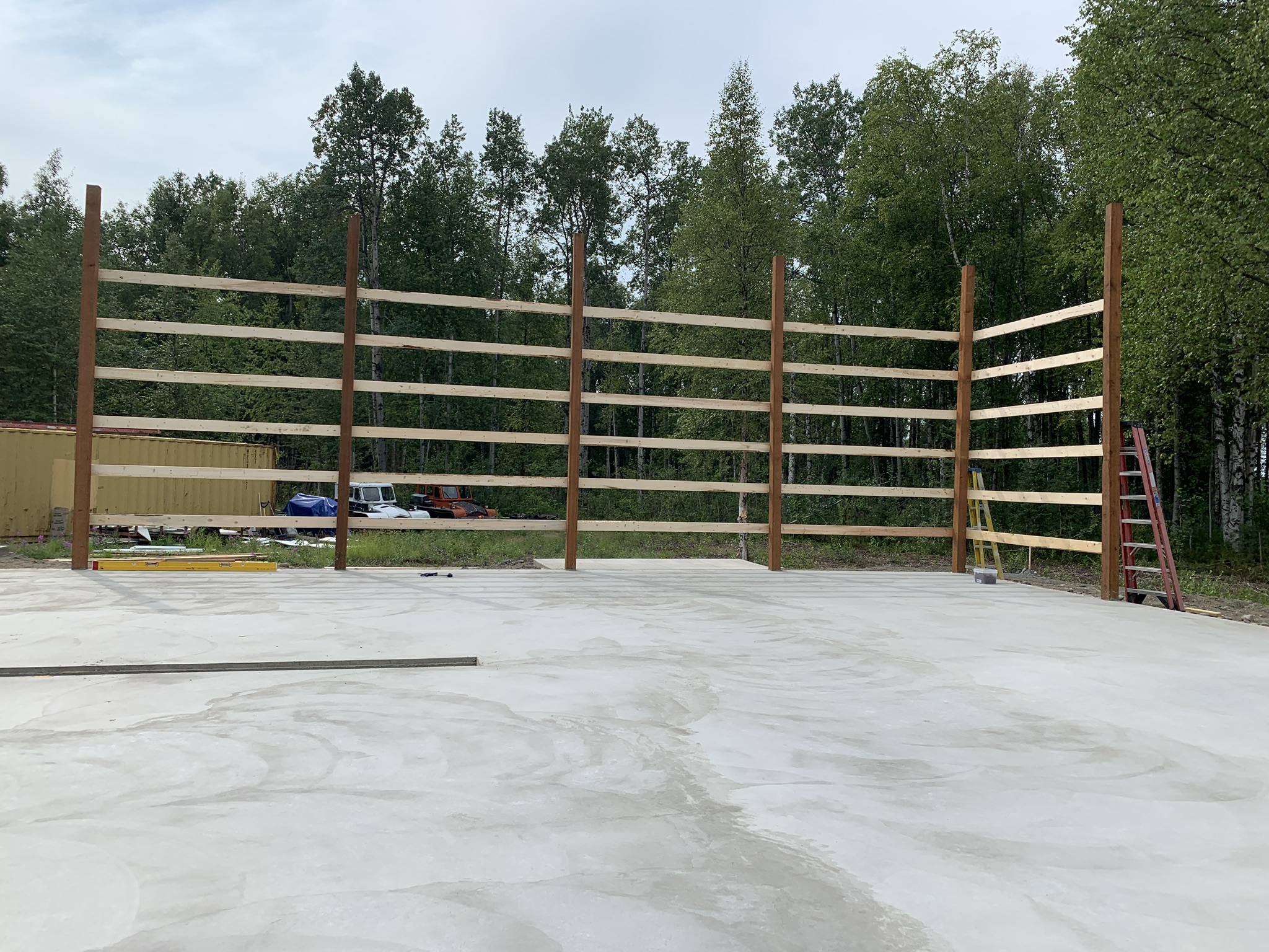
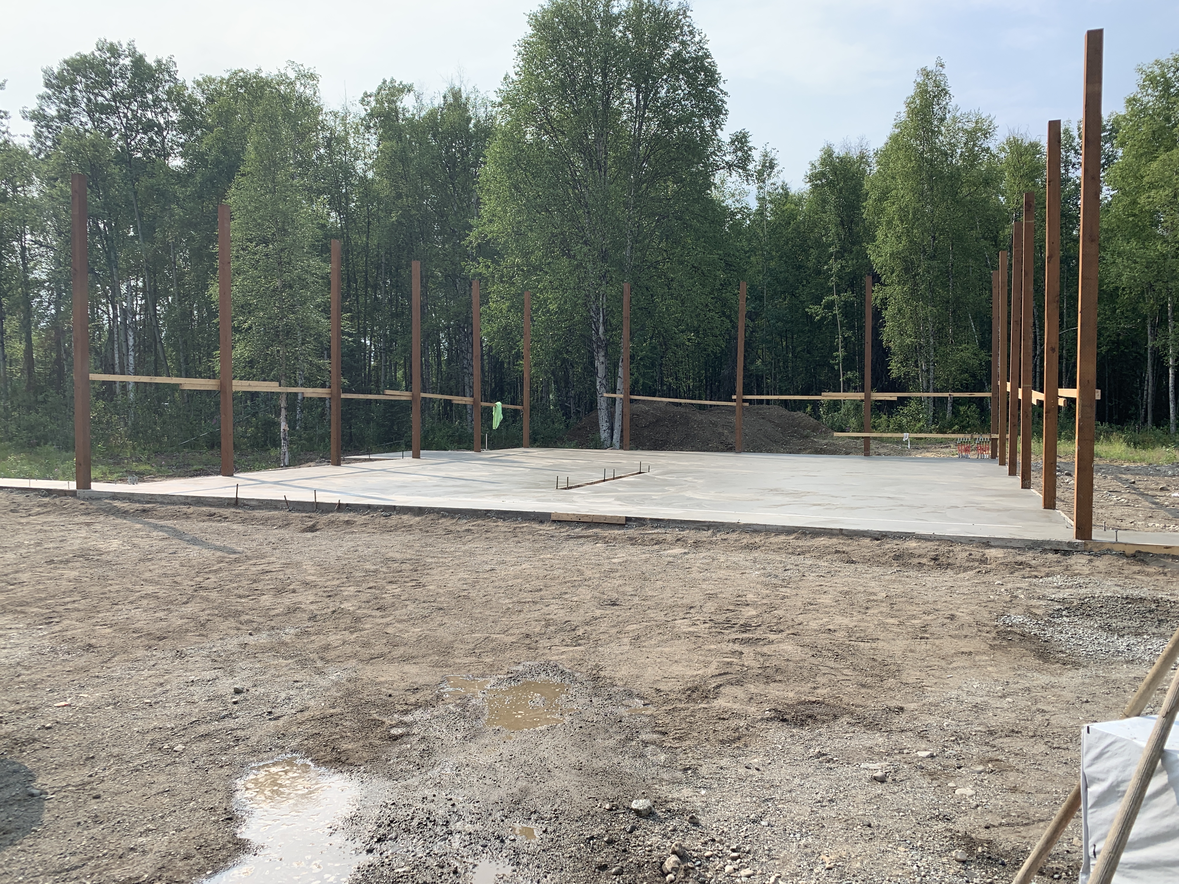
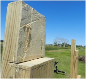 I purchased a building back in February and just now starting to build. I have the Poles up and concrete down. Now I’m starting to install the Trusses. I have a question about the truss layout, on drawing S-4 It shows to drop the Back truss 7-5/8” and then the next set of trusses it looks like I need to drop the outer truss 7-5/8” also which will allow my purlins to be installed on top and tie into the 2nd truss. I have two questions. 1: The two interior trusses I understand they must set on a 3” ledger that I cut from the post, the way the post is laid out on plans is 6×4 on the outer post and the would only leave me with just an ½” of post to attach my Trusses to. 2: I understand the drop in truss’s but the purlins actual measurement is 7-1/4 and I setting them at 7-5/8” according to drawings. I just wanted to confirm that was correct.
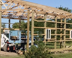 The load, however was not from the wind (as might have been expected), but instead, it was from one of the crew standing in the middle of it!
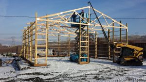 Prior to the adoption of the International Building Codes, wall members which did not support a brittle finish material (e.g. drywall), were not limited in how far they could deflect.