Tag Archives: wind exposure B

Stud Walls Between Post-Frame Columns for Alternative Sidings

Stud Walls Between Post-Frame Columns for Alternative Sidings?

Reader JAKE brings up an interesting question:

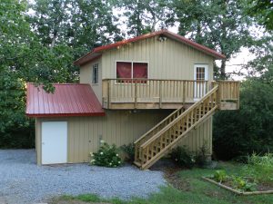
“Hello! I was looking at the blog for a question I had about wall girts for post frame buildings… I was wondering that if a form of siding is installed on the building other than sheet metal, needing wall sheathing, would it be structurally sound to frame 2×6 walls between your 12’ apart posts and not have wall girts? Just attaching the wall sheathing to the posts and 2×6 walls in between? Thank you!”

Pole Barn Guru BlogMike the Pole Barn Guru says:
Before we get to your structural question, a few words. 6×6 columns are notorious for having dimensional variability. I have seen them run as much as 3/4″ over dimension. An over 5-1/2 inch dimension would mean your columns are going to project either inside or outside of your stick framed interior wall.

Now we get into structural soundness.

My concern is how to adequately transfer loads from the top of the stud wall into columns.

Walls lie within two wind zones. Zone 5 is within 10% of least building footprint dimension, with a minimum of four feet. It applies to any secondary member with over 50% of its length within this zone. Provided your building is 60 feet or less in length and width and bays are 12 foot, it would not be applicable for your case.

Wind pressure is derived from wind speed “V”. For an Exposure B (protected from wind in all four directions) site, here are applicable loads in psf (pounds per square foot) for secondary components and cladding members (with mean roof height less than or equal to 15 feet) and a fully enclosed building:

MPH       PSF (ASD – Allowable Stress Design)

95       10.527

100     11.664

105     12.86

110     14.114

115     15.426

120     16.797

125     18.226

130     19.713

135     21.258

140     22.862

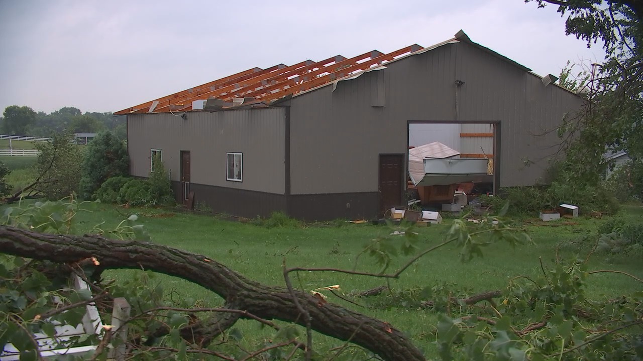
All of these loads are negative, meaning your wall is trying to be sucked out of your building.

Arbitrarily picking 110 mph and a 10 foot wall height (if this is for a residence, or accessory building to a residence, then wall heights are limited to 11’7″ by IRC – International Residential Code Section R301.3):

Total load on a 12′ section of wall (by length) would be: 12′ x 10′ tall x 14.114 psf = 1693.68#. One half of this load is transferred to ground through bottom plate, and one half of remainder must be transferred through top plates to column or 423.42#.

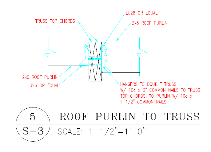
When not nailed into end grain (through a plate into end of stud would be end grain and value is reduced x 0.67; toe-nailing reduces value x 0.83) a 10d common nail (3″ long x 0.148″ diameter) nail has a laterally loaded strength value of 102.022# with Hem-Fir or SPF lumber.

How to attach the wall section to the column is your challenge.

In order to nail through end stud into columns, connection at top of stud (nail driven through top plate) would take 423.42# / (102.022# x 0.67) = 6.19 nails. Probably unrealistic to expect to drive 7 nails into top of a single 2×6 stud.

How about toe-nailing plates to column? 423.42# / (102.022# x 0.83) = 5 nails. While ugly, this might be doable.

Ultimately, connection of top plates to columns would probably be cleanest by use of a Simpson Strongtie strap such an LSTA12.

For our example I have picked a fairly low design wind speed, so higher wind speeds will increase loads and make connections even more difficult. As building mean eave height increases beyond 15 feet, applied loads will increase. In order to meet enclosed building requirements – plan upon use of wind load rated doors (other criteria also apply to meet enclosed requirements), else applied loads may increase. Don’t have a protected site? Exposure C places a load approximately 20% greater than Exposure B on your building.

In summary, while what you propose might work, it should be checked by whatever engineer is placing his or her stamp on your building plans.

Wind Exposure and Confusion Part III

Cliff Notes for Wind Exposure
Been following along reading my articles on wind exposure? OK – so here is my “Cliff Notes” version – in generalized, simple terms:
Wind Exposure B is a site protected from wind in all four directions, within 1500 feet, by trees, hills or other single-family home sized buildings. This would include building sites in residential neighborhoods and wooded areas. If your picturesque view is under ¼ mile, then this is probably you.
Wind Exposure C is open to wind in one or more directions, for 1500 feet, with only scattered obstructions generally less than 30 feet tall in any direction. This would include building sites in flat open country and grasslands. Can you see ‘forever’ in one or more directions and your
‘forever’ does not include a body of water over a mile wide? You are Exposure C.
Very few people actually have Wind Exposure D. This would be areas facing unobstructed large bodies of water (over 5000 feet in width) or within 600 feet of a qualifying shoreline (water over 5,000 feet in width), whether unobstructed or not. Examples include ocean shorelines, wide lakes or rivers (Columbia, Missouri, Mississippi, etc.).
I am always amazed when I get a request for a quote from someone claiming Exposure D…and they are in mid- Kansas with not even a river, much less a lake within 100 miles!
I also have those folks who insist the “prevailing wind” comes from the one direction they have “protected”, so they want to claim Wind Exposure B – when other three sides are basically totally exposed.  Exposure B determination doesn’t care what side IS protected –just all four
sides ARE protected.  And, although it doesn’t hurt to claim a more restrictive exposure “just to be safe”, it will cost more in many (but not all) cases.  When in doubt, stand on your building site and take photos in all 4 directions, and then take them to your building department for a wind exposure determination.  It’s always best to have your local Building Officials working with you from project beginning.

An Avoidable Building Failure

I had already begun working on this article when I saw on Facebook a great post frame prefabricated wood roof truss setting video (https://www.facebook.com/ruralrenovators/videos/2443278165738995/) posted by Kyle Stumpenhorst of Rural Renovators, LLC (https://rrbuildings.com/).

This is not a paid endorsement for Kyle – however I do believe Kyle really cares about doing a job right. If I personally lived in his immediate service area of Franklin Grove, IL and needed a post frame building erected, I would call Kyle – and wouldn’t ask for bids from anyone else. I am willing to pay for someone who truly takes pride in what they do.

Photo above and excerpts in italics are from a July 29 updated posting at www.fox9.com (for full article: http://www.fox9.com/news/widespread-damage-east-of-twin-cities-after-tornado-reports).

Areas east of the Twin Cities were among the hardest hits spots after storms ripped through Minnesota and Wisconsin on Sunday.

There were at least four reports of tornadoes created by the storms across Minnesota — including one near the area of Scandia — but none have been officially confirmed by the National Weather Service as of Sunday night.

Daniel Kaiser said, “In probably 15, 20, 25 seconds, it was kind of in and out of here so that wind, it didn’t really last too long. I was just kind of amazed to see all of the trees down from the wind we had here.”

Several decades of old trees lay across Daniel Kaiser’s lawn in Scandia. He’s also dealing with some unusual debris.

“That’s one of the solar panels from across the street,” he explains. “It’s amazing how much force that must have been coming through here carrying these things because they aren’t light.”
One solar panel ended up stuck several feet off the ground in a tree. Onlookers were surprised by the damage.

“I’ve never seen that,” said Rob Thompson. “Almost 52 years old and I’ve never.”
Down the road, the damage was even worse.

“The siren went off and Terry said, ‘Go downstairs’ and so we all went downstairs,” recalls Mark Johnson.
The Johnson’s roof was ripped off their pole barn.
“It just got underneath the roof and ripped the whole roof off and sucked all of the insulation out.”

I can tell you right now what happened, and then will show why. This entire roof – steel roofing and wood roof purlins was lifted off from roof truss system because of a poor connection. Long time readers will recall me mentioning how most engineering failures are due to poorly designed or improperly installed connections.

Many Midwest pole building suppliers and contractors provide buildings with sidewall columns anywhere from seven to 10 foot on center. A single pole barn roof truss is placed at each column. 2×4 roof purlins are installed (on edge) across purlin tops. One popular supplier uses a nine foot spacing with 20 foot long purlins to span two ‘bays’ (a bay being space between truss columns).

Design wind speed is 115 mph from 2015 IBC (International Building Code) Figure 1609.3(3). This is based upon IBC Risk Category II for buildings like your home. For this purpose, we will assume an Exposure B for wind site (building in the photo is Exposure C, roughly 20% greater loads). Wind exposure is explained here: https://www.hansenpolebuildings.com/2012/03/wind-exposure-confusion/.

Using appropriate calculations wind load (uplift) for components and cladding in this area of roof is 33.547 psf (pounds per square foot). Weight of roof purlins and steel roofing can be used to resist this uplift (roughly 1.105 psf). This makes our net uplift 32.442 psf.

For the sake of this discussion we will assume purlins are spanning eight feet between truss centers and spaced every two feet. This means each purlin end has 16 square feet of surface to possibly uplift x 32.442 psf or a total of 519.072 pounds.

We are going to attach purlin to top of truss using a 60d pole barn nail (roughly 2/10 inch in diameter). From the 2015 National Design Specifications for Wood Construction (NDS) Table 12.2D with a Specific Gravity of 0.55 (assuming roof truss top chords are Southern Pine – other species may be less) and a nail diameter of 0.200 inches, these nails are good for 109 pounds of resistance per inch of depth of penetration (lbs/in) into truss top chord.

109 lbs/in multiplied by 2-1/2 inches = 272.5 pounds. Because this connection is not controlled by metal strength a load adjustment factor of 1.6 may be applied giving total resistance to uplift of 436 pounds or 19% overstressed.

Even worse would be if a purlin is used to span across two adjacent bays of roof. Using the previous example, our uplift loads at each end would be reduced to 389.304 pounds per end (and working), however at our truss at center uplift would be nearly 1300 pounds!

There does exist some solutions, most economical of width is probably to use engineered joist hangers and place purlins between trusses.