Please Structurally Design My Pole Barn for Free
This is one of those POLE BARN GURU questions which results with a lengthy enough answer I feel I must devote a whole column to it.
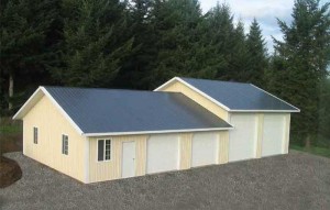
DEAR POLE BARN GURU: Could you please help clarify, for a 40 ft. wide x 64 ft. long x 15 ft. high Pole Barn Building,
What size & kind of posts are needed?
How you would recommend connecting posts to trusses?
Footer depth & construction?
Lateral Wind bracing & Uplift measures?
Would greatly appreciate hearing your recommendations. Thank you! EILEEN in CENTERBURG
DEAR EILEEN: What you are asking for is to have a building engineered, without knowing the parameters the building is being engineered for.
Without the knowledge of your wind loads (including exposure), snow and seismic loads, any answers I would give to you for your pole barn design would most likely be incorrect.
 Post frame buildings also work as a system, so individual components or connections might possibly be adequate, however the entire building fails due to a weak link. This is why I always, always (did I say always) recommend ONLY to invest in a building which is designed by a registered design professional (RDP – engineer or architect) – especially for your particular site.
Some general answers to your questions (answered as if I was going to build this building for myself):
Posts
I would use true glu-laminated columns (not nailed up columns), as they have a high strength to weight ratio, are lighter to work with and tend to be less prone to warp and twist.
Trusses
The post to truss connection would have double trusses set into a notch cut into the top of the column. This prevents the trusses from being able to “slide” down the column in the event of a high snow load. To avoid uplift challenges, the trusses can be bolted or a combination of threaded hardened nails and bolts could be used. In high uplift situations, appropriately sized Simpson HST brackets may prove to be the best design solution.
Footer
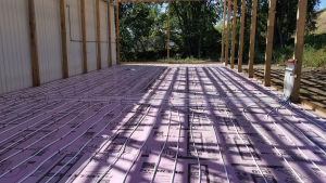
Footer depth and construction – the holes need to extend at least below the frost line, and I tend to use 40 inches as a minimum depth into undisturbed soil. The columns should be floated eight inches above the bottom of the hole then no less than a total depth of 16 inches of premix concrete poured into the hole. The diameter of the holes will depend upon the loads being placed upon them, as well as the assumed bearing strength of the soil at the site.
Do not attempt to use concrete “cookies” – https://www.hansenpolebuildings.com/2012/08/hurl-yourconcrete-cookies/ or bags of sackcrete – https://www.hansenpolebuildings.com/2012/11/concrete/
Siding
Provided there are not excessive door openings in endwalls, in most cases the utilization of the proper screw for attachment of steel to framing the steel skin should be able to adequately transfer the imposed loads: (https://www.hansenpolebuildings.com/2012/08/this-is-a-test-steel-strength/
Bracing
Here is some reading on bracing which you might find helpful: https://www.hansenpolebuildings.com/2016/03/diagonal-bracing/ and https://www.hansenpolebuildings.com/2012/01/post-frame-construction-knee-braces/
Good luck with your pole barn design.
Mike the Pole Barn Guru
 I’ve found what may be a quicker and easier solution. Pro-footer® manufactures a patent pending product called the “one pour reinforcement cage”. The cage rather reminds me of my futile days smacking golf balls around at the driving range – as a similar wire basket was used for practice balls.


