Tag Archives: column embedment

Steps to Minimize Snow Load Failures

The following article will appear in April 2019’s Component Manufacturing Advertiser magazine (www.componentadvertiser.com).

Early every year NFBA (National Frame Building Association) holds its annual Frame Building Expo – where thousands of post-frame builders, design professionals and vendors meet for three days filled with break-out sessions, guest presenters and of course a trade show.

In 2019’s Expo, one breakout session was, “Avoiding Common Building Failures in the Post-Frame Industry” presented by Ryan Michalek, P.E. of Nationwide Insurance.

The “trailer” for this session was, “Would you find it surprising that Nationwide Insurance’s loss experience with post-frame buildings is disproportionately represented by newly constructed facilities? The company’s loss history is full of buildings that are less than 5 years old and that fail when subjected to their first moderate wind or snow loading event or to a modest commodity-loading cycle. This presentation discusses the common oversights in post-frame building design and construction which lead to building loss and offers strategies to eliminate these oversights.”

I quizzed Mr. Michalek myself as to how many of these failures were subjected to a structural plan review by a Building Official. His opinion was few, if any, failed buildings were designed by a registered design professional RDP (registered engineer or architect), as they are nearly exclusively “agricultural” structures, exempted from Building Permit processes in many states.

My personal belief – every building should be designed by a RDP, as well as being subjected to structural review by a Building Official. Knowing Insurance Industry size, I questioned why it was Nationwide® and other insurance companies were not lobbying for stricter rules for these now permit exempt buildings. Mr. Michalek minced no words in stating United States agricultural lobby having far more power than insurance industry lobby.

I am just not grokking thought processes of those who would invest in buildings which will underperform or fail structurally, all for saving a few dollars. Considering many failures come from poultry industry buildings, it seems costs and cleanup of a million dead chickens or turkeys would trump a few dollars saved on construction.

What was surprising to me, was an analysis of actual most prevalent failures – although column size and embedment always seem to be big concerns from informed purchasers, it wasn’t a contributor to three major causes of failures: lateral bracing of trusses; purlin to truss connections and unbalanced and snow drift loads on trusses.

Typically builders, when they do install bracing, will just run it laterally from building end to building end. This results in all trusses bending together, as loads being placed upon bracing are not being transferred to a very stiff surface – like a roof diaphragm. By utilization of properly designed “X” braces, lateral loads can be transferred into roof plane, and keeping trusses where they are happiest – upright.

Many post-frame buildings, especially those designed with widely spaced single trusses rely upon nailed purlin-to-truss connections woefully inadequate to resist uplift forces. This becomes even more crucial in critical areas such as “end zones” and close to eaves or ridge. A solution would be to use appropriate engineered hangers to attach purlins.

A third common area of failure occurs from designs where drifting snow causing unbalanced loads has not been accounted for. Roof truss designers have an ability to turn off a “switch” in their engineering design programs accounting for drift loading. This results in a less expensive, although under designed truss. With no structural design review, no plan’s examiner will catch trusses being inadequately or inappropriately designed.

Not only do trusses need to support unbalanced snow loads, so do roof purlins. It’s not unusual for an engineered building to have purlins either spaced closer together, or of higher grade or larger size in roof drift areas.

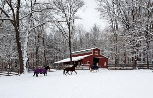
Fast forwarding to 2019’s NFBA Expo – where a frequently heard topic of discussion revolved around a plethora of snow related building collapses in Wisconsin, Minnesota, North and South Dakota. A great majority of these roof failures came from buildings exempted from Building Codes.

While it is impractical, unaffordable or unfeasible to retrofit existing buildings to meet Code loading requirements, we can make changes to minimize or eliminate future failures due to snow. Every time a post-frame building roof collapses, it reflects poorly upon our industry. When prefabricated wood roof trusses fail, truss manufacturers get blamed.

Together these two industries can lobby for changes ultimately making for better and safer buildings.

In my humble opinion, these would include:

Require all buildings over 200 square feet to be constructed from plans sealed by a RDP, as well as to be subject to a structural plan review and field inspections.

Eliminate “agricultural exemptions” from permits.

Eliminate Risk Category I as an IBC option. Risk Category I reduces design loads for snow and wind. This doubles annual probability of failures as compared to Risk Category II.

Eliminate use of Cs to downward adjust top chord live loads due to roof slope and “slipperiness” of roof surfaces. Too many buildings have snow retention systems added to roofs, after completion. This would be all well and good if RDPs and truss technicians were made aware when computing their designs.

Create minimum design dead loads of five psf (pounds per square foot) for both top and bottom chords of roof trusses. Some post-frame buildings have sheathing installed between purlins and roof steel, overloading top chords. Personally, I receive numerous inquiries every week from building owners who now want to install ceilings in their existing post-frame buildings and find their building’s trusses are not designed to support this weight.

Have Building Departments re-evaluate values used for snow (and wind) loads in their jurisdictions. Allstate® Insurance has a TV commercial featuring actor Dennis Haysbert. Haysbert sits in an open field and questions why there have been 26 “once in 500 years storms” in last decade, when term alone implies they should only happen every 500 years.  An increase of design snow load of only 15% cuts annual probability of a failure in half!

Hopefully we will learn from this past winter’s collapses and become proactive together to make for better and safer buildings!

How Should I Backfill My Pole Barn Holes?

How Should I Backfill My Pole Building Holes

This is a subject which is repeatedly brought up. Usually it is ones who are constructing a post frame building which was not designed by a registered design professional (RDP – architect or engineer). The wrong answer could easily lead to a catastrophic failure of the building!

Reader JOE in ROCHESTER writes:

“I am in the process of building a relatively small pole building. 16x24x8. I’m having trouble finding the right answer to the back filling the pole question. The local Inspector will be coming to measure the depth of the holes (42” to the top of the footer) but other than that they didn’t give me any spec on back filling or diameter and thickness of the concrete footer. My question is what do you recommend for footer size and how should i back fill the holes around the poles? 42” of concrete around the poles seems like excessive to me and just back filling with earth doesn’t seem right either. Any advice would be much appreciated. Thanks.”

Mike the Pole Barn Guru advises:
My educated guess is the local building authorities issued you a permit to construct without requiring you to submit engineer sealed plans. All this ends up doing is leaving things to chance – which you are quickly finding out. Column embedment (depth and diameter of the holes), thickness of concrete footing, concrete collars, etc., are a function of many different variables.

Among these variables include – the soil bearing capacity of the earth at your site, weight of building with a code minimum snow load, design wind speed and exposure, building eave height and roof slope, is it fully enclosed, roof only or some or all of a wall open? Any one of these could affect the outcome.

Ultimately you should have a registered professional engineer or architect design the column embedment for you. From judicious experience, assuming a fully enclosed building with wind rated doors and properly tied into a four inch nominal concrete slab on grade, your engineer would probably require these as minimum: eight inch thick 18 inch diameter concrete footings. Two sticks of 1/2″ diameter rebar driven through the lower portion of the column, one each direction and sticking past the column four to six inches each side. A Concrete bottom collar probably 10 inches tall and the same 18 inch diameter, with the balance of the hole backfilled with compactable materials well compacted.


One Pour Reinforcement Cage

The original Hansen Pole Buildings column encasement design, had the pressure preservative columns placed to the base of an augured hole. Pre-mix concrete was then poured around the lower 16-18 inches of the column to form a bottom collar. The bond strength between concrete and wood was sufficient to enable the assembly to resist both gravitational forces (settling) as well as uplift.

For further reading on the concrete to wood bond strength: https://www.hansenpolebuildings.com/blog/2013/04/pole-barn-post-in-concrete/

There were, however, a few Building Officials who just could not wrap their heads around this as a design solution – they wanted to see concrete underneath the columns.

The solution – we changed our design so the base of the columns “float” eight inches from the bottom. By nailing one of the framing members temporarily across the column, at the appropriate depth, it makes for a relatively easy design solution.

By doing this, premix concrete can be monolithically poured into a bottom collar which also provides a concrete footing beneath the column.

footing cage
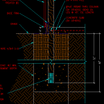
I’ve found what may be a quicker and easier solution. Pro-footer® manufactures a patent pending product called the “one pour reinforcement cage”. The cage rather reminds me of my futile days smacking golf balls around at the driving range – as a similar wire basket was used for practice balls.

The one pour reinforcement cage base is designed to ensure a solid footing when placed in the hole. Six inches up from the base is a relatively open platform which supports the bottom of the column as well as allowing six inches of concrete to flow under the base of the post, during a single pour.

The Pro-footer™ cage increases the shear and tension strengths developed by the concrete and reduces cracking of the concrete. It is the design of the Pro-footer™ to keep the spacing between the cracks in concrete minimized in order to limit crack width. The width of any such crack is controlled by the proper provision of reinforced concrete provided by the Pro-footer™ wire cage.

Besides the advantage of providing a relatively simple monolithic concrete pour, the Pro-footer™ cage is relatively inexpensive. They are easily applied in the field, their light weight makes them easy to handle and their use does not expose the interior of the column to potential decaying elements, such as occurs in cases where people drill holes through the embedded portion of the column for rebar.

I don’t often find myself attracted enough to a new product to say I would give it a try myself – however the Pro-footer® one pour reinforcement cage could be an exception!

Dear Guru: Size of Concrete Collar; Grounded Metal Siding

Dear Pole Barn Guru is normally my Monday Feature, but lately I’ve gotten backed up on questions – so in honor of Friday the 13th, am hosting an additional segment.  This is why I encourage those with questions to provide email addresses, which are used for nothing other than answering your questions. We don’t SPAM or email you anything other than what you ask for.

If you want a quick answer, please be sure to answer with a “reply-able” email address.

Email all questions to: PoleBarnGuru@HansenPoleBuildings.com

DEAR POLE BARN GURU: We are in a no frost area with no snow load, so why are the post piers so large and deep?? NOT DIGGIN IT IN CA

DEAR NOT DIGGIN’ The column embedment (depth and diameter of the holes) has to do several things, including:

Resisting uplift – the columns, their encasement (the concrete attached to the base of the column) and the “cone” of soil above the concrete bottom collar, must have sufficient mass to keep the building from being literally “sucked” out of the ground. (Think of the force applied to an umbrella on a windy day.)

Resisting overturning – prior to the engineering studies done over the past few decades, the “rule of thumb” was 1/3 of the column should be below grade. Modern technology has allowed this design to be far more scientific, as well as generally reducing the depth of the columns.

Keep the building from settling – while you state your building has no snow load, the information on your order has your building designed for a ground snow load (Pg) of 35 pounds per square foot. The footings must be able to support the dead weight of the structure PLUS any live loads which would be applied to it. These live loads include the weight of any snow, or potential snow. Your building also is designed for a light storage load attic space. Any roof truss design with this type of load, must be designed to support a 10 psf (pounds per square foot) dead load across the entire truss bottom chord (12,960 total pounds on your 36′ x 36′ building) by Code. The storage area adds another 20 psf for another 8640 pounds. All of these weights have to be distributed by the concrete encasement, to the soils beneath the building, with minimal settlement.

Your building has been designed with a 2000 psf soil bearing capacity, which is higher than what is allowed by most California jurisdictions. The use of this number, has actually allowed for the concrete diameters of most of the holes to be far smaller than if a lower number had to be used.

DEAR POLE BARN GURU: Should the sheet metal (steel) siding and roofing of a post frame building be grounded?

If so should it be bonded to the ground bar or ground rod of the building’s electrical panel?

My pole building sheet metal does not contact the earth. The metal is painted and may have electrical bonding between the panels either at a common fastener or bare spots in the finish.(or maybe not, who knows)

Also the electrical panel is installed on wood framing with no fasteners touching the metal siding. The electrical panel ground bar is bonded to ground rods but the bond is insulated from the metal siding.

I have looked at similar buildings(wood frame) in my area and see no evidence of grounding of the sheet metal except by accidental contact.

This building is used as a machine shop/storage building, no farm animals.

Is there a right way? or a better way? or does it make any difference? ZAPPED

DEAR ZAPPED: Should it be grounded? Maybe. Is it required to be grounded? No. As I admit to being “electrically challenged”, my best recommendation would be to contact your local licensed electrician. Here is the “skinny” from the NEC (National Electrical Code):

Structural metal. If exposed structural metal that forms a metal building frame is likely to become energized, you must bond it to one of these [250.104(C)]:

  • Service equipment enclosure
  • Grounded neutral service conductor
  • Grounding electrode conductor, if sized per Table 250.66
  • One or more of the electrodes of the grounding electrode system

This rule doesn’t require you to bond sheet metal framing members (studs) or the metal skin of a wood frame building , but doing so is a good practice. Size the bonding jumper for the structural metal per Table 250.66, based on the feeder or service conductors that supply the building (or structure). This bonding jumper must be:

  • Copper where within 18 inches of earth [250.64(A)].
  • Securely fastened and adequately protected, if exposed to physical damage [250.64(B)].
  • Installed without a splice or joint, unless spliced by irreversible compression connectors listed for the purpose or by the exothermic welding process [250.64(C)].


DEAR POLE BARN GURU: How to install an equipotential ground in the concrete?  Also is it necessary to ground the metal siding and if so best method. CONCERNED IN CALIFORNIA

DEAR CONCERNED: As far as “how” to install an equipotential ground or to ground the metal siding would be questions best answered by your electrician. My concern would be, do you even need to be concerned with this.

From the 2010 CEC (California Electrical Code) Article 547 (the red text highlight is mine):

Equipotential Plane –  “An area where wire mesh or other conductive elements are embedded in or placed under concrete, bonded to all metal structures and fixed nonelectrical equipment that may become energized, and connected to the electrical grounding system to prevent a difference in voltage from developing within the plane.” 

A post frame building is not an “all metal structure”, so the need for a equipotential plane, would not be existent.

The Code also does not require metal siding to be grounded.