Example Builder Warranty
Disclaimer – this and subsequent articles on this subject are not intended to be legal advice, merely an example for discussions between you and your legal advisor.
I cannot express strongly enough how important to both builders and their clients to have a written warranty in any agreement.
WARRANTIES: There is no warranty applicable to the building and is expressly in lieu of all other warranties available under any State or Federal laws, expressed or implied, including any warranty of all labor, material, product and taxes will be paid for and there will be no potential lien claim against Purchaser’s property upon completion of the work and following final payment by Purchaser to Seller.
Products supplied by third party suppliers, manufacturers and sub-contractors to the project are warranted only to the extent that the suppliers and manufacturers of those products provide a warranty.
In the event that a defect is discovered in one of these products, Seller will assist Purchaser in securing repair or replacement of these products under the warranty provided by the third party supplier or manufacturer. Warranty work is work which was correctly and completely done initially, but becomes non-operational or dysfunctional following occupancy or use by Purchaser. No retainage or holdback will be allowed for warranty work.
Seller expressly warrants to the original noncommercial purchaser(s) and only the original purchasers.
That if any part of a Seller constructed post frame building, as covered by this warranty, proves to be defective due to materials or workmanship, under normal use and service, for two (2) years, that defective part will be repaired or replaced, subject to the terms and conditions contained in this Warranty.
Seller hereby assigns to Purchaser all rights under manufacturer’s warranties. Defects in items covered in manufacturer’s warranties are excluded from coverage of this limited warranty, and Purchaser should follow the procedures in the manufacturer’s warranties if defects appear in these items.
For ten (10) years.
Any solid sawn or glu-laminated (pressure treated to a minimum UC-4B) structural columns that fail due to decay or insect damage, unless said column has been exposed to animal wastes.
The original building roof structure, if damaged directly by snow loads because of the failure of any prefabricated roof truss or trusses to meet design specification. Subjecting your roof system to greater loads than those set out on the face of this Agreement, any unspecified ceiling loads, or modifying the trusses in any way voids all Warranties.
Any major structural defects which are defined as being an actual defect in a load-bearing portion of the building which seriously impairs its load-bearing function to the extent that the building is unsafe. For purposes of this definition, the following items compromise the structure of the building:
- Load bearing columns,
- Floor or ceiling joists,
- Beam, trusses and rafters.
For Two (2) Years:
Any roof leaks due to defects in material or workmanship, expressly excepting where the building has been connected to an adjoining structure, in roof valleys, or at roof slope changes to which cases, no warranty applies.
Any other building parts which prove to be defective in material or workmanship.
This warranty period shall commence on the date of the acceptance of the building by the Purchase or Purchaser’s occupancy of the building, whichever comes first.
This warranty contained wherein is void in situations where:
- Installation is not made in accordance with the instructions supplied by Hansen Buildings.
- The actual operation or use of the product varies from the recommended operation or intended use.
- There is a malfunction or defect resulting from or worsened by misuse, negligence, accidents, lack of or improper performance of required maintenance by the original purchaser.
- The building is altered or added onto, unless by Seller.
- Seller is not notified within twenty four (24) hours of problems due to snow loads.
- Purchaser fails to take timely action to or damage.
- Anyone other than Seller’s employees or agents or subcontractors have been on the building roof.
- Purchaser fails to make final payment per terms of sale.
Equipment such as fans, HVAC, gutters, downspouts, walk door locksets, other equipment not manufactured by Seller, site work, concrete, doors, windows, interior finishes, mechanical or electrical systems are excluded from this warranty.
The Purchaser expressly agrees to fully and timely pursue all available remedies under any applicable insurance agreement before making claim under this warranty.
In the event Seller repairs, replaces or pays the cost of repairing or replacing any defect covered in this warranty for which Purchaser is covered by insurance or a warranty provided by another party. Purchaser must assign proceeds of such insurance or other warranty to Seller, to the extent of the cost to Seller, of such repair or replacement.
Any claims for defects under warranty must be submitted in writing to Seller within the warranty period and promptly after discovery of the claimed defect, describing the defect claimed and date of building completion, before Seller is responsible for correction of that defect. Written notice of a defect must be received by Seller prior to the expiration of the warranty on that defect and no action at law or in equity may be brought by Purchaser against Seller, for failure to remedy or repair any defect about which Seller has not received timely notice in writing.
Purchaser must provide access to Seller, during normal business hours to inspect the defect reported and, if necessary, to take corrective action. A reasonable time should be allowed for inspection purposes. If, after inspection, Seller agrees, at its sole option to repair or replace only the defective materials or workmanship within the first three months from date of building completion at NO COST to the Purchaser. Thereafter Seller shall assume the cost of material and labor for any warranty work upon advance payment by the Purchaser of a one hundred dollar service payment for each incident under this warranty. The obligation of Seller, under this warranty, shall be performed only by persons designated and compensated by Seller for that purpose, and is subject to all other provisions of this warranty.
The provisions of this Warranty are the full and complete warranty policy extended by Seller, and are expressly in lieu of all other warranties, expressed or implied, including any warranty of merchantability or fitness for a particular purpose. These warranties may not be transferred or assigned. The liability of Seller shall not exceed the cost to Seller for repairing or replacing damaged or defective material or workmanship, as provided above, during the warranty period.
THE WARRANTY STATEMENTS CONTAINED IN THIS LIMITED WARRANTY SET FORTH THE ONLY EXPRESS WARRANTIES EXTENDED BY SELLER FOR ITS BUILDING AND THE PROVISIONS HEREOF SHALL CONSTITUTE THE PURCHASERS EXCLUSIVE REMEDY FOR BREACH OF THIS WARRANTY. IN NO EVENT WILL SELLER BE LIABLE TO THE PURCHASER FOR INCIDENTAL OR CONSEQUENTIAL DAMAGES OF ANY KIND FOR BREACH OF AN EXPRESS OR IMPLIED WARRANTY ON THE BUILDING; PROPERTY DAMAGE, PERSONAL INJURY , OR ECONOMIC LOSS IF OCCASIONED BY SELLER’S NEGLIGENCE, EVEN IF SELLER HAS BEEN ADVISED OF THE POSSIBILITY OF SUCH DAMAGES.
Some states do not allow the exclusion or limitation of incidental or consequential damages, so the above limitations or exclusions may not apply to you. This warranty gives you specific legal rights and you may also have other rights which vary from state to state.
Purchaser shall promptly contact Seller’s warranty department regarding any disputes involving this Agreement.
Seller and Purchaser agree that this limited warranty on the building is in lieu if all warranties of ability or workmanlike construction or any other warranties, express or implied, to which Purchaser might be entitled, except as to consumer products. No employee, subcontractor, or agent of Seller has the authority to change the terms of this warranty.
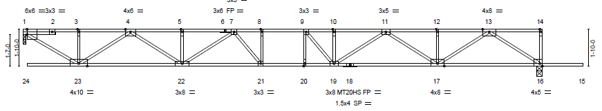
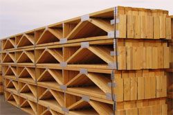
 Prefabricated wood floor trusses were an apt decision. They easily out span dimensional lumber or I-joists and due to their open webs, holes do not need to be strategically placed for plumbing and electrical. Until pre-COVID, they generally made for a quite affordable floor. With larger spans, came greater loads at floor truss ends, resulting in more use of LVLs, so it was not a perfect system.
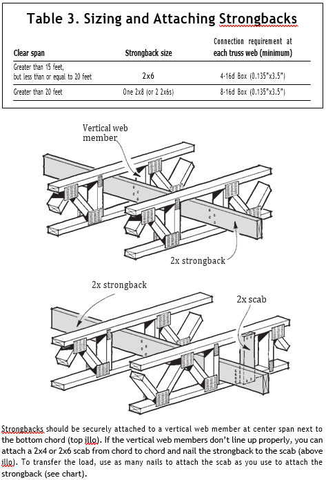
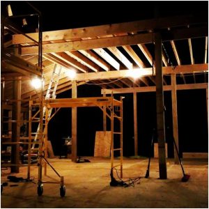
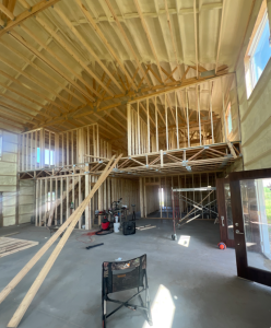
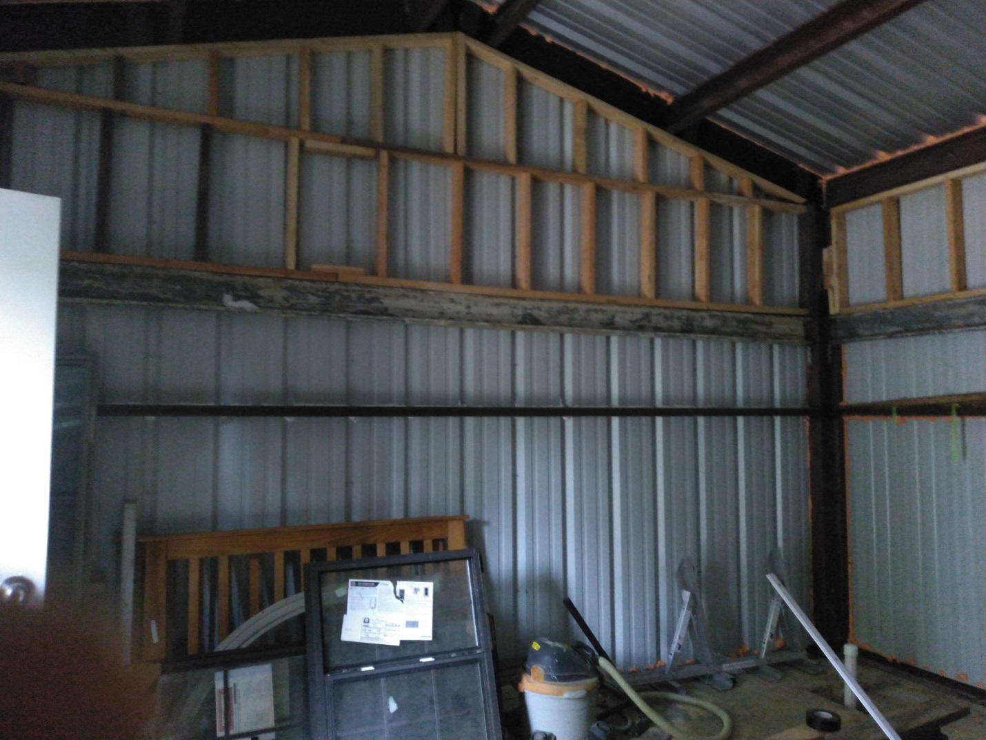
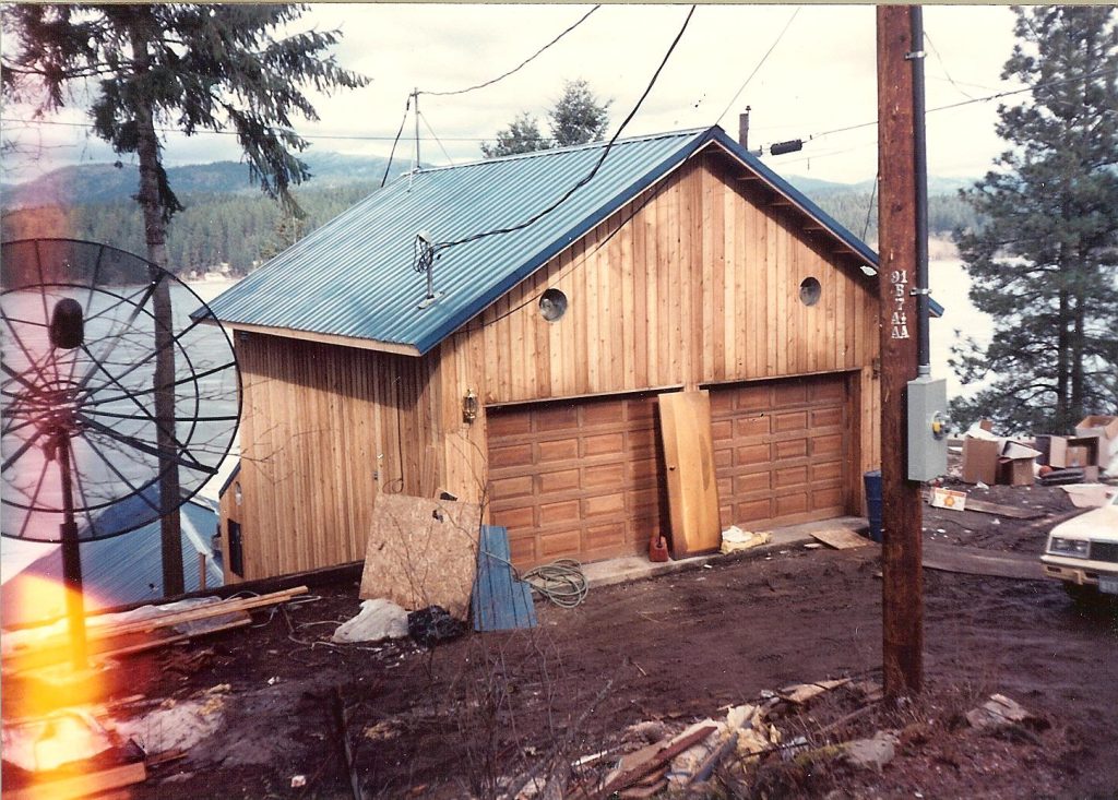
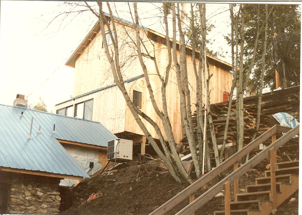
 Lots of considerations to be taken into account when adding a second floor to an existing post frame building, especially if connecting to current structural framing members.
 DEAR TAMI: Provided footings beneath your CMU wall are adequate in dimension, probably. In areas of your existing wall where ICC ESR approved engineered wet-set brackets for columns will be placed, existing blocks will need to be removed and replaced, so brackets can be properly poured into wall.
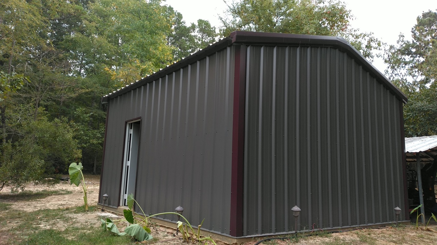
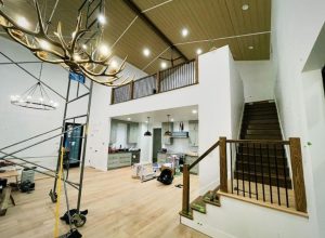
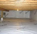 You could condition your crawl space – this would require a 6mil or thicker, well-sealed vapor barrier to cover underlying soil and up perimeter walls to floor joists. There would be no vents with this method, however an air-circulating device must be provided. Perimeter walls should be insulated using either closed cell spray foam or rock wool batts.
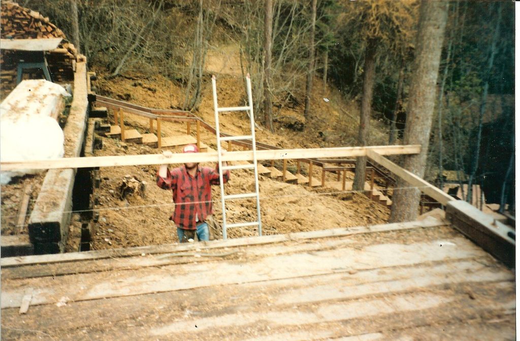
 Thank you for your service sir.
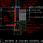
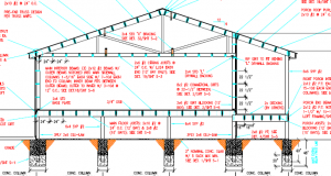 Well Jerry, a simple answer is yes, you need to support floor joists at the exterior wall. Beyond this things begin to get more complex and should only be done with a Registered Professional Engineer being involved.
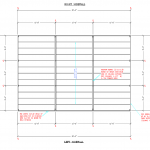
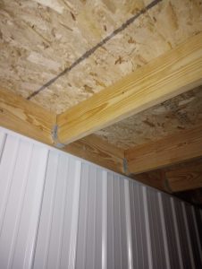 HY floor joists are wood prefabricated I joists. Let’s take a look at Chris’ proposed design solution (please keep in mind, any structural design solution should be reviewed by your building’s engineer to confirm structural adequacy):