This Wednesday the Pole Barn Guru addresses reader questions about common gable post frame footings, weight limitations for a building delivery and the possible solutions, and what types of foundations Hansen Buildings can design for in Weld County Colorado.
DEAR POLE BARN GURU: What is a common gable post footing compared to a main truss post footing, where are these located on a building? ELLIOT in PINEHURST
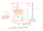 DEAR ELLIOT: Most post frame buildings are rectangular, with peaks (a point or gable) on opposite ends. Building codes require a minimum footing thickness of six inches, or an ICC-ESR approved alternative (like these https://www.hansenpolebuildings.com/2014/05/footingpad/). Main truss post footings will be located along the eave (side snow slides off of) and support roof trusses (hence ‘main truss post’). As they carry more weight than endwall (peak of roof ends) columns, they will typically be larger in diameter. Your building’s engineer sealed plans will specify locations and diameters required to adequately support weight of building (including applied loads). This is not a place to guess or scrimp, as you really wouldn’t be happy with any of your columns settling.
DEAR POLE BARN GURU: 50x 50 x 16 pole barn approximate weight, limited by bridge on property? NEIL in TULSA
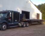 DEAR NEIL: A far greater issue than weight of your building package (roughly 20,000 pounds total depending upon features) will be weight of trucks making deliveries (many weigh 32-40,000 pounds when empty). We have had many clients in a similar situation to yours and materials can often be offloaded onto a flat trailer you can pull behind a pickup, or similar, in order to get into challenging jobsites. Biggest concern will be 50 foot long roof trusses, as truss truck is going to be a semi pulling usually a 48 foot long trailer. You might want to consider making a donation to your local high school’s football team in order to have them physically pick up and carry individual trusses across bridge and to your site.
DEAR POLE BARN GURU: What type of foundations are used in Weld County, CO for pole barn homes? Insulated slab on grade? Crawl space? BRENT in KERSEY
 DEAR BRENT: We have provided roughly 300 fully engineered post frame buildings to our clients in Colorado (many of these in Weld County). Types of foundations for post frame homes are nearly as varied as are our clients. We’ve done full or partial basements (including walkout or daylight) in block, poured concrete or ICF; crawl spaces (both conditioned and non-conditioned) as well as slabs on grade (both with heated slabs and under floor insulation or unheated slabs with perimeter insulation). Embedded columns are going to be least expensive and strongest, however we can also design and provide for cases with ICC-ESR approved wet set brackets. With most sites in Colorado, it is beneficial to involve a Geotechnical engineer to do a proper assessment of your site’s soil conditions and bearing capacity in order to assure best outcome. Often jurisdictions will make this a requirement. Here is some extended reading on slabs vs. crawl spaces: https://www.hansenpolebuildings.com/2019/03/slab-on-grade-or-crawl-space/
 Well Jerry, a simple answer is yes, you need to support floor joists at the exterior wall. Beyond this things begin to get more complex and should only be done with a Registered Professional Engineer being involved.


