10 Important Things to Consider When Building a Pole Barn
By Andi Croft.
Andi Croft is a freelance writer whose main interests are topics related to home design, business, technology, and travel. This is brought about by her passion about going around the world, meeting people from all walks of life, and bringing along with her the latest tech to enhance her adventures.
Within the construction domain, the magnetic appeal of pole barns remains potent, presenting a versatile and economically sound solution for diverse requirements ranging from agricultural storage to workshops.
Yet, the expedition from conceptualization to realization demands meticulous planning and thoughtful consideration of numerous pivotal factors.
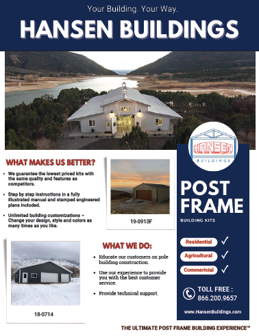
This useful guide ventures into the exploration of ten critical elements to consider when building a pole barn.
1. Smart Pole Barn Planning
The genesis of any successful project lies in thoughtful planning. Before installing the first post, envision the purpose of your pole barn. Is it a haven for livestock, a storage facility, or perhaps a workspace?
Define your needs and consider future expansion possibilities. Strategic planning ensures your pole barn meets current requirements and adapts seamlessly to evolving needs.
Consider the pole barn’s layout, optimizing space use and ensuring efficient workflow. Whether incorporating additional storage lofts or allocating specific zones for different functions, a well-thought-out plan serves as the architectural blueprint for success.
2. Site Assessment and Conditions
Undertaking a comprehensive site assessment is akin to laying the foundation for success. Examine soil quality, drainage patterns, and topography to determine the most suitable location for your pole barn.
Factors include sunlight exposure and prevailing winds, as these elements play a pivotal role in the long-term functionality and durability of the structure.
Conduct a soil percolation test to assess drainage capabilities, preventing potential flooding or soil erosion. Evaluate the land’s natural features, ensuring that the chosen site maximizes energy efficiency through proper orientation and utilization of natural light.
3. Hiring Professional Builders
Crafting a pole barn necessitates a blend of artistry and precision. Currently (and for the foreseeable future) there is a nationwide shortage of building erectors. Many high quality erectors are booked out well into 2024 (some even 2025). We would strongly encourage you to consider erecting your own building shell. Otherwise, engage seasoned professionals who specialize in pole barn construction.
Building from fully engineered, site specific plans ensures the structure adheres to industry standards and local building codes. A proficient team expedites the construction process and minimizes the likelihood of costly errors.
Examine the credentials of potential builders, seeking out references and examples of past projects. If an erector tells you they can begin quickly it is generally either a big red flag, or there is a chance you are being price gouged. ALWAYS THOROUGHLY VET ANY CONTRACTOR https://www.hansenpolebuildings.com/2018/04/vetting-building-contractor/. Ask about their technologies – construction software, project collaboration tools, estimation, submittals, etc.
4. Understanding Zoning Rules and Regulations
Navigating the labyrinth of zoning rules and regulations is paramount to a hassle-free building process. Before breaking ground, acquaint yourself with local ordinances governing setbacks, height restrictions, and land use.
Compliance with these regulations expedites permitting and safeguards your investment against potential legal ramifications. Consult with local authorities or zoning officials to clarify any ambiguities and ensure your pole barn project aligns with community guidelines. https://www.hansenpolebuildings.com/2013/01/planning-department-3/
Failure to adhere to zoning regulations can lead to costly delays and legal complications, underscoring the importance of due diligence in this project phase.
5. Materials Selection
The choice of materials significantly influences your pole barn’s longevity and aesthetic appeal. Explore options for posts, trusses, and roofing materials, considering factors like climate, intended use, and budget constraints.
Opting for durable and weather-resistant materials ensures that your pole barn weathers the test of time while requiring minimal maintenance. Consider the environmental impact of materials, exploring sustainable options that align with your values and long-term goals.
The selection of high-quality materials enhances the pole barn’s structural integrity and contributes to its overall visual appeal and resilience against the elements.
6. Engineering and Design
The engineering and design phase is the architectural heartbeat of your pole barn. Collaborate with professionals to create a blueprint that seamlessly integrates functionality with aesthetics.
Precision in structural design enhances the visual appeal and guarantees the pole barn’s structural integrity, especially in regions prone to extreme weather conditions.
Consider the incorporation of advanced design software and technology to create 3D models, allowing for a more immersive understanding of the final product.
Engage in open communication with the design team, ensuring the finalized plans align with your vision while adhering to safety and regulatory standards.
7. Foundation and Anchoring Methods
The foundation is the bedrock of any construction project, and pole barns are no exception. Evaluate various foundation options and choose one that aligns with your specific needs.
Selecting an appropriate foundation from traditional concrete pads to modern alternatives like helical anchors ensures stability and longevity. Consider the soil composition and load-bearing requirements when determining the foundation type.
Engage with structural engineers to assess the most suitable anchoring methods, considering soil stability and potential seismic activity. A robust foundation supports the structure and safeguards against settling structural issues over time.
8. Effective Insulation is the Key
Beyond structural considerations, the comfort and utility of your pole barn hinge on effective insulation. Depending on the purpose of your structure, explore insulation options that regulate temperature and minimize energy costs.
Incorporating proper insulation not only enhances the livability of the space but also contributes to long-term cost savings. Evaluate insulation materials based on their R-value, ensuring they meet or exceed local building codes for energy efficiency.
Consider factors such as moisture resistance and fire-retardant properties to enhance the safety and durability of the insulation. A well-insulated pole barn creates a comfortable environment year-round, making it conducive for various uses.
9. Construction Time Frame
Time is a critical factor in any construction endeavor. Establish a realistic timeline, considering weather conditions and potential setbacks.
A well-planned construction schedule streamlines the process and allows for contingencies, ensuring that your pole barn is completed within the stipulated timeframe. Factor in seasonal considerations understanding how weather patterns may impact construction timelines.
Regular communication with the construction team facilitates proactive problem-solving and promptly addresses unforeseen challenges, preventing unnecessary delays.
10. Budget and Cost Management
Finances are the backbone of any project, and meticulous budgeting is non-negotiable. Factor in all expenses, from materials and labor to unforeseen contingencies.
A detailed budget prevents financial surprises and facilitates informed decision-making throughout the construction journey.
Create a comprehensive budget that includes a buffer for unexpected expenses, ensuring that you have the financial flexibility to address unforeseen challenges without compromising the quality of the project.
Regularly review and update the budget as the project progresses, keeping a keen eye on cost management to prevent budget overruns.
Conclusion
In the symphony of construction, building a pole barn requires a harmonious blend of foresight, expertise, and meticulous execution. From planning your pole barn construction to the finishing touches, each step plays a crucial role in shaping a structure that stands the test of time.
By considering the ten pivotal aspects outlined in this guide, you pave the way for a pole barn that meets your immediate needs and becomes a lasting testament to the artistry and precision of thoughtful construction.
Remember, the investment in careful planning and execution is not just in a structure; it’s in the creation of a functional and enduring space tailored to your specific needs and aspirations.
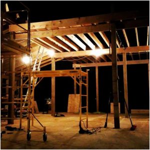
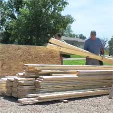
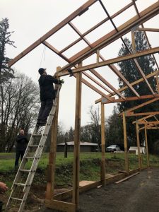
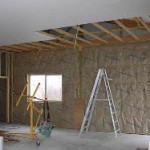 When buildings have no endwall overhangs, all roof trusses are placed with bottom chords at same height. Ceiling joists can be placed with bottom of joists and bottom of trusses at same height and connected with joist hangers.
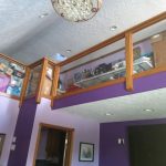 1. It Looks Amazing
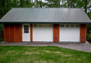
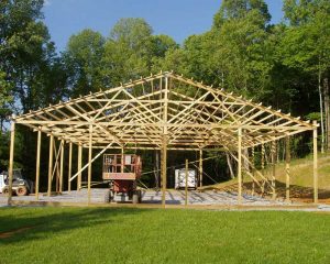
 XYZ Lumberyard’s design solution was to place a column every 10 feet with single trusses five foot on center in between the columns on “truss carriers” (basically headers). I put the same information into our state-of-the-art post frame design software and came up with sidewall columns as 6×8 Southern Pine, stressed to 60.5% of capacity.
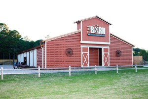 What the good (yet uniformed) mayor is missing is a “pole barn” (more properly referred to as a post frame building) can look just like any other building.
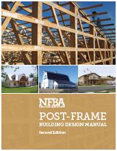 The NFBA has risen to the occasion with the recent introduction of the new Post-Frame Building Design Manual! The second edition of the manual—and the first new edition since 2000—is the ultimate tool for post-frame design. Eight chapters, 200 pages, and hundreds of photos, diagrams, illustrations and design tables cover everything you need to know about designing with post frame.
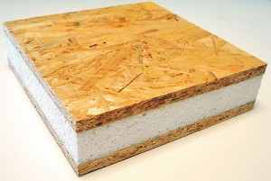 What are SIPs?
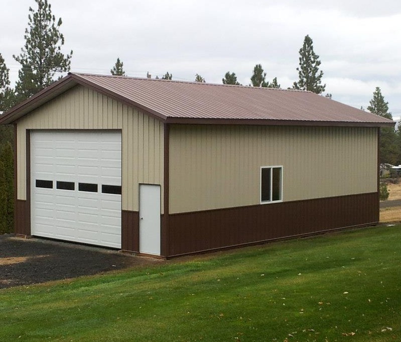
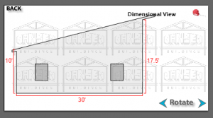 “I will be building a single slope (roof and 3 sides covered with corrugated steel) pole barn similar to one of your designs online. My ideal design is 20 by 30 with 1 foot roof overhang. The structure consists of (3) 20 x 10 bays. High side to be 12 feet and low side to be 10 feet with bay entry at high side. I will only consider steel posts (8) for the vertical pole construction. For the roofing material please include 2 each opaque roof sheathing for each bay (natural lighting). Design to include high wind (50 mph) with 18″ snow load. Please provide a detailed bill of material including foundation (30 to 36 inch footing depth (no slab) with bid. I will be requesting engineered drawings. The shipping destination is xxxxx zip code so please include shipping total and tax in bid.
 Besides the shirts and miniature golf, there was one characteristic I noticed about many of the houses built along the Grand Banks – they are mostly built on top of platforms which are eight to ten feet off the ground and supported by pressure preservative treated wood columns embedded into the ground.
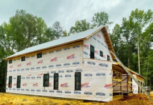 Friday, October 11, at 5:25 p.m. a tornado touched down about 10 miles northeast of Dumont, (just across the border into MN) in a soybean field. As the tornado moved to the northwest, it struck a barn which suffered significant structural damage. The steel siding from the barn was found over 50 yards away, with one piece speared eight inches into the ground and stuck standing upright!


 How thoroughly are members (framing pieces) checked? Every direction possible for climactic forces (such as wind, rain and snow) and seismic forces, as well as construction loads and the weight of the building itself. Our engineering program runs all the mathematical calculations as if these forces are applied to every piece of the building. It then chooses the appropriate lumber and parts to put them together (ledgerloks, bolts, LSTA straps, nails etc.) to ensure every building is designed to not only meet, but exceed stated code requirements.
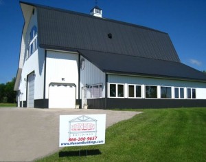 benefit is there will be fewer holes to dig. Unless one would happen to be part gopher, most are like me – we hate digging holes. With a passion. In many cases, the “more posts” are smaller in size or lower strength posts…..in which case, what was the point?
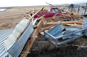 Now I know 18 mph does not sound like much, but in the formula to convert from miles per hour, to pounds per square foot of load, the wind speed is squared! While 138 is only 15% faster, the effective load placed on the building is over 32% more. Huge difference.
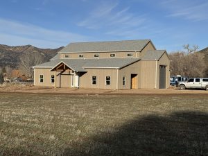 This is how buildings work to resist lateral wind loads when they have few or no openings.


