Tag Archives: Frank Woeste

Builder Says

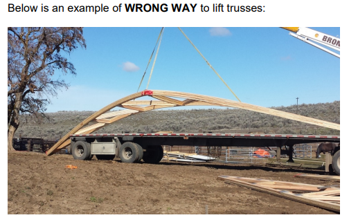
Builder Says, “These designs are the Worse”!

Like all good stories begin…..

“It was a dark and stormy night”

Oops, wrong beginning!

Once upon a time I was a post frame building contractor. From 1991 until 1999 my construction company could only have been described as being prolific – at one time we had as many as 35 crews erecting buildings in six states.

I had a few advantages going into being a post frame building contractor – architecture school, managing several (and later owning) prefabricated metal connector plated roof truss plants, and having provided nearly 7000 post frame building kit packages from my lumberyard.

mr owl tootsie roll popMy most important advantage was a thirst for knowledge. One of my favorite childhood books was 1967’s “The Way Things Work” by Neil Ardley and David McCaulay. I read it cover-to-cover repeatedly. This same thirst for wanting to know how things work led me to Dr. Frank Woeste at Virginia Tech. He challenged me with learning structural calculations involved in what made post frame (pole barn) buildings work.

This, in turn, led me to join ASAE (American Society of Agricultural Engineers) where I was a member of their structures committee. It also led me to be humble as I learned as I knew more, there was so much more to learn. I became an NFBA member – and found there was more than a single ‘right way’ to build post frame buildings.

Now it seems every small town in America has one or more post frame ‘builders’ and I will use this term ‘builder’ lightly as owning a jacked up 4×4, having a big dog and a loud stereo are not necessarily qualifiers for being a good builder. While there are actually some good builders (and a few great ones), far more a rule than an exception is “Chuck-in-a-truck” who believes he (or she) is Builder Bob – a legend in their own mind!

A Hansen Pole Buildings’ Do-It-Yourself client recently posted photos of their framed post frame building with commercial bookshelf girts.

Before being banned from the Facebook group for use of colorful language, builder Jason had this to say about this client’s photo:

“These designs are the worse! I don’t understand why anyone would do it this way. I really don’t understand why any company would promote such a design to a DIY. Book shelve wall girts are the weakest way to build building. All seams in wood is stacked. Not staggered. Toe nailed also is week. And if any system requires you to “hide” something or “never see it”, It’s a bad design! Just run wall girts on out side of post and stagger seams. Simple!”

Well Jason, not everyone has your narrow view of structural design solutions (or your grasp of English composition).

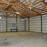
People (both builders and DIYers) do bookshelf girts because they are, at a minimum, over 300% stronger in supporting wind loads than externally mounted girts (based upon 2×6 material of same grade at same spacing). They are also more resistant to deflection by more than 1300%. Moreover, with proper dimensional sizing, they allow for creation of an insulation cavity where clients can do interior finishes without having to add more framing.

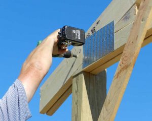
Jason appears to have a belief staggering joints on externally mounted wall girts somehow makes a building stiffer! It is the use of diaphragm design to create a stiff roof plane to support column tops making a building more rigid, not some close to insignificant contribution from girts. Our ‘builder’ went off on his rant before noticing the ends of each girt are solid blocked to columns at each end and no toe nails are involved in their fully engineered connection (nor was anything required to be hidden).

Thinking of hiring a builder to erect your new post frame building? Look for one who is open to considering multiple design considerations rather than “this is how we have always done it and always will”.

For extended reading on bookshelf girts please read: https://www.hansenpolebuildings.com/2020/04/creating-extra-work-in-barndominium-framing/

Safety Information for Post Frame Truss Installation

Safety Information for Post-Frame Truss Installation

The following article, written by Frank Woeste, P.E., appeared in the February 2018 edition of The Component Manufacturing Advertiser, and is reprinted here, in its entirety. The BCSI-B10 document referenced is included within the Hansen Pole Buildings’ Construction Manual as part of every building kit package provided by Hansen Pole Buildings.

The recent jobsite installation accident involving truss construction, “Three injured in north Washington County barn collapse,” is a reminder of the incredible value of BCSI-B10 for truss installation contractors who install trusses spanning up to 81-ft. and spaced up to 12-ft. on-center. In some collapse cases that I have investigated, the installation contractors had successfully installed typical “house trusses” without incident, but had not previously installed 60-ft. (or greater) widely-spaced trusses, 14–16 ft. above grade. The safe erection of typical long-span trusses used in pole barn (post-frame) construction is challenging and requires knowledge of special truss erection techniques.

While I am not aware of details of the planned construction and Washington County accident, the news report sounds all too familiar. From the news report, the situation sounds like a typical failure mode of long-span trusses during the installation process:

“The men were putting up trusses….when they noticed ‘a sway or a bend in the trusses’.”

The “sway or a bend” is typically caused by “compressive stresses” in the top chords. When the compressive stress reaches a critical level, buckling of the chords can occur and cause a catastrophic collapse.

Fortunately for contractors, guidance on how to safely erect long-span widely-spaced trusses was developed and published in 1998 by the Truss Plate Institute (TPI). The 1998 document, HIB-98, was later revised and updated by SBCA and TPI, and published as BCSI-B10 by SBCA: http://support.sbcindustry.com/images/publication_images/b10.pdf.

It should be noted that the special installation techniques presented in the B10 were written by a small group of about 5–6 post-frame engineers with long experience in both post-frame design and truss installation as well. While the BCSI-B10 method for safely installing widely-spaced long-span trusses is well illustrated for the contractor, the purpose of this article is to draw attention to important building design details and installation steps that must be coordinated by the Building Designer and truss installation contractor.

Creating a “Truss Sandwich” for Safety

The proven technique used by the most experienced design-build post-frame designers and contractors is to create a “truss sandwich” by extending the gable end wall columns up to the top chords of the gable end truss. As depicted by Figure H from HIB-98 Post Frame Summary Sheet shown here, the gable end trusses are stabilized from “rollover” by structural connections between the end-wall columns and top and bottom chords.

Importantly, these safety precautions have been maintained during the document’s evolution from HIB-98 to BCSI-B10. Page 2 of BCSI-B10 provides the following instruction under Important Notes on Limitations of Recommendations:

  1. For gable style roofs, the end-walls shall have columns that extend to the top chord of the gable end truss with adequate contact between the top chord and column for a structural connection. The gable end trusses are stabilized against rollover by connecting the top and bottom chords to the end-wall columns or engineered bracing system.

This focus on end-wall stabilization is critical to successful installation (picture 1).

Another important feature of the “truss sandwich” method is to stabilize the truss heels against rollover by extending the side-wall columns to the mid-height of the truss heel plus a structural connection between the truss heel and side-wall column. The BCSI-B10 Important Notes section on page 2 continues with Notes 4 and 5:

  1. Side-wall columns extend above the mid-height of the truss heel at the connection of the column and the truss.

    5. Truss heels are connected to columns or headers (i.e. beams, girders) to resist rollover at the heel.

An example detail for meeting the requirement of Notes 4 and 5 is shown in the picture 2.

Conceptually, based on the full implementation of Notes 3, 4 and 5, the gable end trusses and truss heels are stabilized against rotation. Thus, the building design details inherently enhance the likelihood of a safe truss installation process by virtue of the fact that the truss support columns provide support to the trusses when they are lifted onto the roof and (positively) connected to the side-wall columns.

Once the truss heels are stabilized by the side-wall column connection, roof purlins (acting as Continuous Lateral Restraint [CLR]) can be installed at the Maximum Spacing Between Rows of Lateral Restraint per Table 1 on page 5 of B10. In Table 1, the maximum spacing between rows of lateral restraint, either 10, 8, or 6-ft on-center, accommodates the later installation of purlins at 2-ft. on-center. From B10 Table 1, the application of the Top Chord Temporary Lateral Restraint Schedule is limited:

IMPORTANT NOTE: Table 1 is applicable for symmetrical triangular metal plate connected wood trusses with pitched top chords of 3:12 or greater and flat bottom chords. Other truss types are expressly excluded. … FOR TRUSS CONFIGURATIONS, SPANS AND/OR TOP CHORD GRADES NOT COVERED BY TABLE 1, CONSULT A REGISTERED DESIGN PROFESSIONAL.

Care must be taken at each step to ensure proper installation.

Chronological Steps are Critical for Success

Beyond the BCSI-B10 recommendations for critically important wall-column design details that enable the wall framing to help stabilize the trusses during installation, a unique feature of B10 for post-frame is the detailed sequence of steps needed to ensure a safe truss installation. On page 3 under TEMPORARY INSTALLATION RESTRAINT/BRACING PRINCIPLES, it states:

Use the following chronological steps to provide temporary installation restraint/bracing for truss installation.

In this section, you will find four pages describing four detailed Steps in chronological order, that is, 1, 1.1, 1.2, 2, 2.1–2.3, and so on. The order of installation work matters such that all forces present and generated during the truss installation process have a “complete load path” to the columns, braced walls, and eventually to the ground.

Permanent Bracing Addressed

BCSI-B10 also addresses permanent bracing. Pages 7 through 12 contain design data and figures that clearly show the need and position of “diagonal braces” for stabilizing continuous lateral restraint (CLR) bracing. This practice would help mitigate what I have observed throughout my career—the collapse of long buildings (400–600 ft.) with webs having one or two CLRs and, at best, only a couple diagonal braces. On page 9, Figures Q, R, and S depict the diagonal bracing required for web members. This information is important for all parties using long-span and widely-spaced trusses.

Opportunity for Component Manufacturers

Component manufacturers have an excellent opportunity to inform post-frame/pole-barn project customers on the availability of BCSI-B10 Summary Sheet and its value for accomplishing a safe installation. This critical information is easy to obtain and distribute.

In my opinion, the 12-page document (in color), https://docs.sbcindustry.com/sample/113, is a “truss safety treasure” for the post-frame method and common applications that range from barns to schools. To my knowledge, the method or special technique for long-span widely-spaced truss installation has been successful without a reported accident.


Evolution of The Pole Barn Guru and his Building Philosophy

Today we’d like to revisit the “Evolution of The Pole Barn Guru and his Building Philosophy”

In my early years, tremendous quality was not necessarily the strong point. It was the ability to offer a very reasonably priced building and deliver it quickly. My buildings were pretty much the same as everyone else I competed against. Business grew and I started being able to hire employees. Jim Betonte left the steel roofing and siding industry and began a construction business which offered labor to people who wanted our building kits erected. In the mid-80’s M & W joined the National Frame Builders Association (NFBA) and started to become better educated on the “post frame” industry on the whole.

The real deal changer – in October 1985 I met Frank Woeste. Frank was an Agricultural Engineering professor at Virginia Tech and what he knew about pole buildings was staggering. In exchange for me traveling to Blacksburg, Virginia to teach one of his classes for a day, Frank gave me my first engineering design software for pole buildings and the printout of the programs in a computer program called “Basic”.

Frank motivated me to want to make better buildings and to know why it is they worked the way they did from an engineering standpoint. From

his program printout, I taught myself Basic programming and wrote more complex and varied programs than the ones which just calculated post, girt and purlin sizes.

My buildings gradually changed – steel stopped being fastened with ringshanked nails in 1982, using first galvanized, then later color matched screws. Green lumber was replaced by kiln dried lumber, much of it (especially larger sizes such as 2×6 and 2×8 with machine stress rated lumber). Utility graded skirt boards and 4×6 columns were upgraded to #2 and better. Pressure treated timbers were treated for structural in ground use, rather than “or refusal” (basically, in many cases, just coated with treating chemicals by the treatment plants).

By 1987 I had joined the American Society of Agricultural Engineers (ASAE) and the International Conference of Building Officials (ICBO). At the time, ICBO was writing the Uniform Building Code, which was adopted throughout much of the United States. The late 80’s were heady times for the ASAE as the structures committee I was a member of, was developing and putting into practice many of the standards now utilized for modern pole building structural design.

Frank Woeste and Don Bender (now a professor at Washington State University in Pullman), began holding commercial post frame design classes, which I first took as a student, and later assisted with. Often, the example buildings for the class were structures of mine.

While I owned M&W we received recognition from the State of Oregon for our donation of a building to earthquake ravaged Irkutsk, USSR. We were featured in newspapers such as the Capitol Press and magazines such as Frame Building Professional. We were also named as one of the 50 largest users of steel roofing and siding in the United States for the decade of the 1980’s. We were even featured on the morning national television program in South Korea!

In 1989, I was elected to a 3 year term on the board of directors for the National Frame Builders Association. To the best of my knowledge, I was the first board member from west of the Mississippi River.

After some 6600 building kits sold in 13 western states, Canada, Mexico and Saipan, I sold M & W Building Supply to Jim Betonte in 1990 and moved back to Spokane. My brother Mark had worked in sales for me at M & W and in 1991 he returned to Spokane as well. We formed Momb Building Systems and began constructing buildings in the Spokane area. Mark left the business in 1992 to return to school and the name was changed to Momb Steel Buildings. Business thrived and in 1993 Apex Roof Truss was begun to produce trusses and provide the lumber packages for our buildings.

Besides Washington, I became a registered contractor in Oregon, Idaho and Montana. At the height of business, we had as many as 35 crews building in six states. In one single county alone, we built over 200 buildings in a single year.

Mike The Pole Barn Guru Featured in Frame Building Professional Magazine

Further improvements to pole building design were made. In the early 90’s we added trims which were not regularly used along the I-5 corridor.  Base trim to keep rodents out, J Channel at tops of walls, overhead door jamb trim, trims on fascias and varges with overhangs, eavelight trims with sidelight panels) all of which made for a far more attractive finished product. The first big structural change was to notch the trusses into the columns to provide direct bearing, instead of attaching them to each side of the columns. Later, we physically doubled up the trusses nailing them face-to-face, instead of blocked apart. At the same time we went to joist hanging all roof purlins between the trusses, instead of placing them lapped over the top of the truss pairs.

This now allowed for the roof panels to be predrilled before installation, which kept all screw lines straight and greatly eliminated the potential for leaks.

At an Alumax testing facility east of Los Angeles, we constructed a full scale roof to test the shear strength of steel panels. Our testing resulted in some surprises. Initially we felt the weak link would be the framing under the steel. We were totally in error and surprised at the results.  Our assembly was done to match industry standards and included fastening the steel to the roof purlins using #10 x 1” screws every nine inches. As we placed horizontal loads into the roof, before ripples even appeared in the steel, the screw started to pull out of the framing. The pull out problem was solved by using 1-1/2” long screws.

The next problem was the steel began to slot beneath the screw grommets. The solution was to use larger diameter screws in the high stress areas (at the eave and ridge) and to place screws in this area on each side of each high rib, rather than along one side only. Only after all of the screw issues were solved, were we finally able to test the steel to failure.  The results showed some fairly significant values. The results of this test are published in the NFBA Post Frame Building Design Manual  https://bse.wisc.edu/bohnhoff/Publications/Copyrighted/NFBA_Design_Manual.pdf See Table 6.1 (assemblies 13 and 14).

After the test was completed, the Alumax design engineer, Merle Townsend designed a screw specifically to solve the weaknesses demonstrated by the test. Labeled as the “diaphragm” screw (https://lelandindustries.com/productpdfs/page%2001.pdf) this 1-1/2” part features a larger diameter shank than standard screws. A side benefit of this screw is that the larger diameter helps prevent the screw heads from twisting off during installation.

To this day, these screws remain a stable part of my building design, and have rarely (if at all) has this great improvement been equaled by any other pole building company.

Stay tuned for the final episode of “From Cradle to now…Mike the Pole Barn Guru” as he expands from four states…to fifty!


Post Frame Safe Rooms

I’ve admired Dr. Frank Woeste, P.E. since I first picked up an article authored by him, which lead to us hanging out on his front porch in Blacksburg, Virginia in October of 1985 discussing bollards. Over the years Frank has done his best to attempt to cram post frame building structural design information into my head – and amazingly I have actually retained a small portion of it! And used it!
In the April 2017 edition of “The Component Manufacturing Advertiser” appeared Dr. Woeste’s article on, “A “Truss Frame” Safe Room for Protecting Your Family?”.
I enjoyed this excerpt:
“I wonder out loud if MPC wood trusses could be used to design and construct a “prefabricated truss-frame” storage shed/safe room building that would safely resist the FEMA recommended wind speeds? With the requisite hold-down-hardware embedded into the truss-frame, the building could be delivered to the site ready for the concrete foundation work needed to secure the shed/safe room.”
The complete article may be read here: https://www.componentadvertiser.com/Portals/0/Downloads/Library/1704/1704%20Frank%20Woeste%20Truss%20Frame%20Safe%20Room.pdf
Being the curious sort I am, I actually downloaded FEMA P-320 (Taking Shelter from the Storm: Building a Safe Room for Your Home or Small Business). And I cruised over the plans which have been provided.
After doing so, I am firmly convinced post-frame (pole) buildings would be ideal for the purpose of safe rooms. The FEMA stick frame version could be converted into post frame. This would pose significant investment advantages for the average building owner in two major areas.
The first significant savings is going to come from the foundation. By using pressure preservative treated wood columns embedded into concrete for the foundation, thousands of dollars of footing and foundation costs can be eliminated.
The second (and most important) would be the safe room building can be constructed by the building owner(s) without the need to hire an expensive General Contractor to do the labor.
Ready to protect YOUR family?

Roof Only Pole Buildings Take II

Roof Only Pole Buildings – Again

Roof Only Building

Roof only pole buildings are most often appealing for one reason, consumers believe they are going to take fewer materials – after all there are no walls! Therefore, be less expensive!

An interesting article, written by Eric Beavers (COO of Armstrong Steel Buildings) appeared recently in Rural Builder Magazine, detailing the challenges of engineered design for roof only all steel buildings. The full article can be read here: https://www.constructionmagnet.com/rural-builder/the-peculiar-thing-about-a-roof-only-steel-building

I appreciated Beavers’ comment, Finally, here’s the big take-away from all this. Some steel building sales people and even some contractors are going to tell your customers that a roof-only structure is going to cost him less than a sheeted building. This should be a huge red flag for your customer. It means they don’t understand the basics of engineering. I get it—as I said, not a lot of people do, but that doesn’t make it ideal, or even OK.”

My long-time readers will recognize the name Frank Woeste (no, not the German born Frank Woeste of Frank Woeste Trio jazz music fame). If you are a LinkedIn member, you can read Frank’s bio at: https://www.linkedin.com/pub/frank-woeste-ph-d-p-e/24/b20/194

For the few of you who didn’t read Frank’s bio, I will summarize it by saying I should hope to someday know as much about post frame buildings and their design, than he has forgotten!

When it came to be questioned about roof only pole buildings, Frank’s advice was to just not do them – period.

I’ve railed about roof only buildings in the past: https://www.hansenpolebuildings.com/blog/2014/04/hay-barn/

There are some cases where a roof only structure is the best design solution. For these building owners, they pay a premium (as compared to an enclosed or partially walled structure) for their roof only building in the form of one or more (or all) of the following:

Larger diameter holes

Deeper holes

More concrete backfill in holes

Larger dimension columns

Increases in prefabricated roof truss member sizes/grades/steel truss connector sizes

More truss bracing

Increased fasteners requirements, especially in truss to column connections

Purlins – closer spaced/larger dimension

Considering investing in a roof only pole building? If so, consider if gaining some “free walls” might not be a bad idea

Evolution of The Pole Barn Guru and his Building Philosophy

In my early years, tremendous quality was not necessarily the strong point. It was the ability to offer a very reasonably priced building and deliver it quickly. My buildings were pretty much the same as everyone else I competed against. Business grew and I started being able to hire employees. Jim Betonte left the steel roofing and siding industry and began a construction business which offered labor to people who wanted our building kits erected. In the mid-80’s M & W joined the National Frame Builders Association (NFBA) and started to become better educated on the “post frame” industry on the whole.

The real deal changer – in October 1985 I met Frank Woeste. Frank was an Agricultural Engineering professor at Virginia Tech and what he knew about pole buildings was staggering. In exchange for me traveling to Blacksburg, Virginia to teach one of his classes for a day, Frank gave me my first engineering design software for pole buildings and the printout of the programs in a computer program called “Basic”.

Frank motivated me to want to make better buildings and to know why it is they worked the way they did from an engineering standpoint. From

his program printout, I taught myself Basic programming and wrote more complex and varied programs than the ones which just calculated post, girt and purlin sizes.

My buildings gradually changed – steel stopped being fastened with ringshanked nails in 1982, using first galvanized, then later color matched screws. Green lumber was replaced by kiln dried lumber, much of it (especially larger sizes such as 2×6 and 2×8 with machine stress rated lumber). Utility graded skirt boards and 4×6 columns were upgraded to #2 and better. Pressure treated timbers were treated for structural in ground use, rather than “or refusal” (basically, in many cases, just coated with treating chemicals by the treatment plants).

By 1987 I had joined the American Society of Agricultural Engineers (ASAE) and the International Conference of Building Officials (ICBO). At the time, ICBO was writing the Uniform Building Code, which was adopted throughout much of the United States. The late 80’s were heady times for the ASAE as the structures committee I was a member of, was developing and putting into practice many of the standards now utilized for modern pole building structural design.

Frank Woeste and Don Bender (now a professor at Washington State University in Pullman), began holding commercial post frame design classes, which I first took as a student, and later assisted with. Often, the example buildings for the class were structures of mine.

While I owned M&W we received recognition from the State of Oregon for our donation of a building to earthquake ravaged Irkutsk, USSR. We were featured in newspapers such as the Capitol Press and magazines such as Frame Building Professional. We were also named as one of the 50 largest users of steel roofing and siding in the United States for the decade of the 1980’s. We were even featured on the morning national television program in South Korea!

In 1989, I was elected to a 3 year term on the board of directors for the National Frame Builders Association. To the best of my knowledge, I was the first board member from west of the Mississippi River.

After some 6600 building kits sold in 13 western states, Canada, Mexico and Saipan, I sold M & W Building Supply to Jim Betonte in 1990 and moved back to Spokane. My brother Mark had worked in sales for me at M & W and in 1991 he returned to Spokane as well. We formed Momb Building Systems and began constructing buildings in the Spokane area. Mark left the business in 1992 to return to school and the name was changed to Momb Steel Buildings. Business thrived and in 1993 Apex Roof Truss was begun to produce trusses and provide the lumber packages for our buildings.

Besides Washington, I became a registered contractor in Oregon, Idaho and Montana. At the height of business, we had as many as 35 crews building in six states. In one single county alone, we built over 200 buildings in a single year.

Mike The Pole Barn Guru Featured in Frame Building Professional Magazine

Further improvements to pole building design were made. In the early 90’s we added trims which were not regularly used along the I-5 corridor.  Base trim to keep rodents out, J Channel at tops of walls, overhead door jamb trim, trims on fascias and varges with overhangs, eavelight trims with sidelight panels) all of which made for a far more attractive finished product. The first big structural change was to notch the trusses into the columns to provide direct bearing, instead of attaching them to each side of the columns. Later, we physically doubled up the trusses nailing them face-to-face, instead of blocked apart. At the same time we went to joist hanging all roof purlins between the trusses, instead of placing them lapped over the top of the truss pairs.

This now allowed for the roof panels to be predrilled before installation, which kept all screw lines straight and greatly eliminated the potential for leaks.

At an Alumax testing facility east of Los Angeles, we constructed a full scale roof to test the shear strength of steel panels. Our testing resulted in some surprises. Initially we felt the weak link would be the framing under the steel. We were totally in error and surprised at the results.  Our assembly was done to match industry standards and included fastening the steel to the roof purlins using #10 x 1” screws every nine inches. As we placed horizontal loads into the roof, before ripples even appeared in the steel, the screw started to pull out of the framing. The pull out problem was solved by using 1-1/2” long screws.

The next problem was the steel began to slot beneath the screw grommets. The solution was to use larger diameter screws in the high stress areas (at the eave and ridge) and to place screws in this area on each side of each high rib, rather than along one side only. Only after all of the screw issues were solved, were we finally able to test the steel to failure.  The results showed some fairly significant values. The results of this test are published in the NFBA Post Frame Building Design Manual  https://bse.wisc.edu/bohnhoff/Publications/Copyrighted/NFBA_Design_Manual.pdf See Table 6.1 (assemblies 13 and 14).

After the test was completed, the Alumax design engineer, Merle Townsend designed a screw specifically to solve the weaknesses demonstrated by the test. Labeled as the “diaphragm” screw (https://lelandindustries.com/productpdfs/page%2001.pdf) this 1-1/2” part features a larger diameter shank than standard screws. A side benefit of this screw is that the larger diameter helps prevent the screw heads from twisting off during installation.

To this day, these screws remain a stable part of my building design, and have rarely (if at all) has this great improvement been equaled by any other pole building company.

Stay tuned for the final episode of “From Cradle to now…Mike the Pole Barn Guru” as he expands from four states…to fifty!