Safety Information for Post-Frame Truss Installation
The following article, written by Frank Woeste, P.E., appeared in the February 2018 edition of The Component Manufacturing Advertiser, and is reprinted here, in its entirety. The BCSI-B10 document referenced is included within the Hansen Pole Buildings’ Construction Manual as part of every building kit package provided by Hansen Pole Buildings.
The recent jobsite installation accident involving truss construction, “Three injured in north Washington County barn collapse,” is a reminder of the incredible value of BCSI-B10 for truss installation contractors who install trusses spanning up to 81-ft. and spaced up to 12-ft. on-center. In some collapse cases that I have investigated, the installation contractors had successfully installed typical “house trusses” without incident, but had not previously installed 60-ft. (or greater) widely-spaced trusses, 14–16 ft. above grade. The safe erection of typical long-span trusses used in pole barn (post-frame) construction is challenging and requires knowledge of special truss erection techniques.
While I am not aware of details of the planned construction and Washington County accident, the news report sounds all too familiar. From the news report, the situation sounds like a typical failure mode of long-span trusses during the installation process:
“The men were putting up trusses….when they noticed ‘a sway or a bend in the trusses’.”
The “sway or a bend” is typically caused by “compressive stresses” in the top chords. When the compressive stress reaches a critical level, buckling of the chords can occur and cause a catastrophic collapse.
Fortunately for contractors, guidance on how to safely erect long-span widely-spaced trusses was developed and published in 1998 by the Truss Plate Institute (TPI). The 1998 document, HIB-98, was later revised and updated by SBCA and TPI, and published as BCSI-B10 by SBCA: http://support.sbcindustry.com/images/publication_images/b10.pdf.
It should be noted that the special installation techniques presented in the B10 were written by a small group of about 5–6 post-frame engineers with long experience in both post-frame design and truss installation as well. While the BCSI-B10 method for safely installing widely-spaced long-span trusses is well illustrated for the contractor, the purpose of this article is to draw attention to important building design details and installation steps that must be coordinated by the Building Designer and truss installation contractor.
Creating a “Truss Sandwich” for Safety
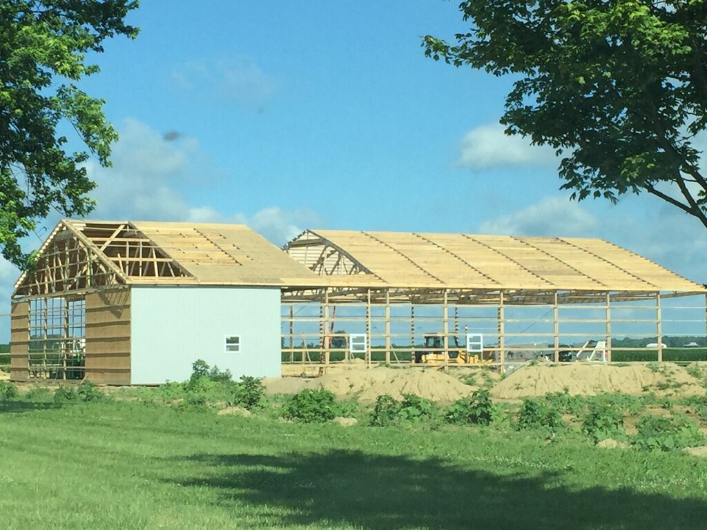
The proven technique used by the most experienced design-build post-frame designers and contractors is to create a “truss sandwich” by extending the gable end wall columns up to the top chords of the gable end truss. As depicted by Figure H from HIB-98 Post Frame Summary Sheet shown here, the gable end trusses are stabilized from “rollover” by structural connections between the end-wall columns and top and bottom chords.
Importantly, these safety precautions have been maintained during the document’s evolution from HIB-98 to BCSI-B10. Page 2 of BCSI-B10 provides the following instruction under Important Notes on Limitations of Recommendations:
- For gable style roofs, the end-walls shall have columns that extend to the top chord of the gable end truss with adequate contact between the top chord and column for a structural connection. The gable end trusses are stabilized against rollover by connecting the top and bottom chords to the end-wall columns or engineered bracing system.
This focus on end-wall stabilization is critical to successful installation (picture 1).
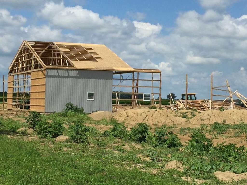
Another important feature of the “truss sandwich” method is to stabilize the truss heels against rollover by extending the side-wall columns to the mid-height of the truss heel plus a structural connection between the truss heel and side-wall column. The BCSI-B10 Important Notes section on page 2 continues with Notes 4 and 5:
- Side-wall columns extend above the mid-height of the truss heel at the connection of the column and the truss.
5. Truss heels are connected to columns or headers (i.e. beams, girders) to resist rollover at the heel.
An example detail for meeting the requirement of Notes 4 and 5 is shown in the picture 2.
Conceptually, based on the full implementation of Notes 3, 4 and 5, the gable end trusses and truss heels are stabilized against rotation. Thus, the building design details inherently enhance the likelihood of a safe truss installation process by virtue of the fact that the truss support columns provide support to the trusses when they are lifted onto the roof and (positively) connected to the side-wall columns.
Once the truss heels are stabilized by the side-wall column connection, roof purlins (acting as Continuous Lateral Restraint [CLR]) can be installed at the Maximum Spacing Between Rows of Lateral Restraint per Table 1 on page 5 of B10. In Table 1, the maximum spacing between rows of lateral restraint, either 10, 8, or 6-ft on-center, accommodates the later installation of purlins at 2-ft. on-center. From B10 Table 1, the application of the Top Chord Temporary Lateral Restraint Schedule is limited:
IMPORTANT NOTE: Table 1 is applicable for symmetrical triangular metal plate connected wood trusses with pitched top chords of 3:12 or greater and flat bottom chords. Other truss types are expressly excluded. … FOR TRUSS CONFIGURATIONS, SPANS AND/OR TOP CHORD GRADES NOT COVERED BY TABLE 1, CONSULT A REGISTERED DESIGN PROFESSIONAL.
Care must be taken at each step to ensure proper installation.
Chronological Steps are Critical for Success
Beyond the BCSI-B10 recommendations for critically important wall-column design details that enable the wall framing to help stabilize the trusses during installation, a unique feature of B10 for post-frame is the detailed sequence of steps needed to ensure a safe truss installation. On page 3 under TEMPORARY INSTALLATION RESTRAINT/BRACING PRINCIPLES, it states:
Use the following chronological steps to provide temporary installation restraint/bracing for truss installation.
In this section, you will find four pages describing four detailed Steps in chronological order, that is, 1, 1.1, 1.2, 2, 2.1–2.3, and so on. The order of installation work matters such that all forces present and generated during the truss installation process have a “complete load path” to the columns, braced walls, and eventually to the ground.
Permanent Bracing Addressed
BCSI-B10 also addresses permanent bracing. Pages 7 through 12 contain design data and figures that clearly show the need and position of “diagonal braces” for stabilizing continuous lateral restraint (CLR) bracing. This practice would help mitigate what I have observed throughout my career—the collapse of long buildings (400–600 ft.) with webs having one or two CLRs and, at best, only a couple diagonal braces. On page 9, Figures Q, R, and S depict the diagonal bracing required for web members. This information is important for all parties using long-span and widely-spaced trusses.
Opportunity for Component Manufacturers
Component manufacturers have an excellent opportunity to inform post-frame/pole-barn project customers on the availability of BCSI-B10 Summary Sheet and its value for accomplishing a safe installation. This critical information is easy to obtain and distribute.
In my opinion, the 12-page document (in color), https://www.sbcacomponents.com/, is a “truss safety treasure” for the post-frame method and common applications that range from barns to schools. To my knowledge, the method or special technique for long-span widely-spaced truss installation has been successful without a reported accident.