I was talking with one of our clients yesterday. His builder was concerned because constructing the new pole building first, and then pouring the concrete slab seemed backwards to him.
Here is the information I shared with the client:
While the preference is to have the building shell completed prior to pouring concrete slabs, at the very least the roof should be installed.
Building columns tend to grow “bull’s-eyes” in the presence of pre-mix concrete trucks. A completed building shell is far more resistant to potential damage. Pouring slabs with columns only in place, adds to the risk of one inadvertently being knocked out of plumb.
 This is not meant to provide the necessary instruction to pour a building slab. Not because the task is beyond a novice’s abilities, although many do contract out this job. Pouring a slab is within most people’s abilities. However, unlike wood framing, which can be corrected if improperly constructed, work on a slab is “set in stone”. Due to this, and the fact so many local codes and practices apply to concrete slabs, I am only touching on this subject. If deciding to personally undertake this task, I suggest talking with local professionals to find out exactly what you are getting into. Have the building inspector (usually a requirement in places requiring a building permit) or a professional inspect work before pouring concrete. If you are less than 100% confident, hire a professional to work alongside you during the concrete pour.
If in “frost country” a sub-base 6” or thicker should be first placed across the site. To maintain frost-free soils the sub-base should be such that no more than 5% (by weight) will pass through the No. 200 sieve, and it is further desired no more than 2% be finer than .02 mm.
Prior to pouring your concrete slab, 2” to 6” of clean and drained sand or sandy gravel is spread below where concrete is to be poured. Mechanically compact fill to at least 90% of a Modified Proctor Density, so as not to cause the slab to sink. Install a good vapor barrier (such as A2V reflective insulation, available through https://www.buyreflectiveinsulation.com ) below any interior pour, to stop moisture from traveling up into the slab through capillary action. Place 3” to 4” of clean and drained sand on top of the vapor barrier to decrease differential drying shrinkage and floor curling. If not using fiber-mesh or similar reinforcement additives to the concrete mixture, place wire mesh or rebar (reinforcing steel rods) in slab center to add rigidity to the concrete to aid in minimizing cracking.
The best insulation product to use under concrete slabs is A2V reflective insulation. A2V is a double layer on air cells, sandwiched between a white vinyl facing on one side and a reflective aluminum facing on the other. Unroll reflective insulation over the prepared site sand or gravel, with aluminum side facing towards the ground (white side up). Overlap by 2” at seams. Run reflective insulation up the skirt board inside by 6”. Seal seams with reflective insulation white vinyl tape or white duct tape. Pour concrete on top of the reflective insulation.
Aluminum side faces away from the concrete because concrete’s high alkalinity attacks aluminum causing the facing to degrade.
Adding sand over reflective insulation will facilitate water drainage during curing time and accelerate installation.
Local building code will dictate such things as slab thickness (usually 4” nominal), wire mesh sizing, gravel or sand layer thickness, and size and rebar location. Many garage or shop slabs also have a center drain. In the event structural engineering for a concrete floor (or any concrete or other masonry footings, foundations, walls, or retaining walls) is required or requested by you, or a building official, a registered professional engineer should be consulted for the design.
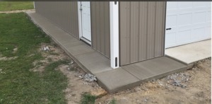
On solid walls of building, the pressure treated 2×8 splash plank will serve as forms for pouring slab. In open wall areas, or across sliding or overhead doors, a 2×4 will need to be temporarily placed as a form.
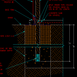
Prior to pouring a nominal 4” (3-1/2” actual completed) thick concrete slab in building, finished, graded compacted fill TOP will be even with splash plank BOTTOM. If a thicker floor is desired, excavate below splash plank bottom, by any slab thickness greater than 4”. In no case will the concrete floor top be even with either the top or bottom of the splash plank. Using any other measure for the concrete slab top will result in wall steel and doors not properly fitting, as well as interior clear height loss.
In other terms – after the floor is poured, when standing inside the building, approximately 3-3/4” of the splash plank will be visible above the top of the slab.
In the event a professional is hired to finish concrete, most often costs can be reduced by paying the local pre-mix company directly for the concrete. Many offer discounts for prompt payment, so do not be afraid to ask. On a properly leveled site, a pre-mix concrete yard will cover an 80 square feet area, nominally four inches thick.
It’s obviously a good idea to completely finish your building at time of construction by pouring your concrete slab. However, I have known of several customers who chose to pour it “later”, thus spreading out costs of their project over time. Whenever you add the concrete floor, carefully follow these introductory points to ensure a level concrete slab…at the correct height.
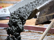 Embedded columns for post frame buildings are almost always both a best and least expensive design solution. Auger holes to depth and diameter indicated on your engineered building plans (always build from engineered plans). If water appears in your hole, it is not a problem, as you can pour concrete into water, professionals do it often. Order pre-mix concrete for your footings and bottom collars with a minimum amount of water content (a W/CM ratio of 0.33 would be ideal).
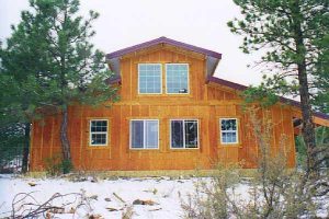 Utterly important will be to remember this mantra – your home has a permanent pressure preservative treated wood and concrete foundation and is a wood framed building with steel (unless your building has something different) siding. You are presenting only absolute truths (unless you neglected to have concrete below or around your building’s columns) – I would never encourage anyone to fib, however success comes from proper presentation.
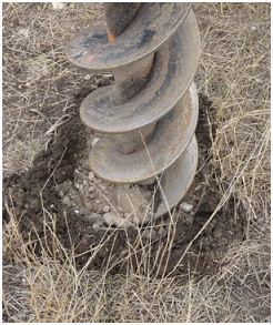
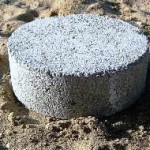
 Even with good soil, your proposed 20 inch diameter concrete cookie is not adequate to properly distribute the weight of your building across the soil. Added to the challenge is the use of attic trusses which is going to further increase the loads on the footings. From the sound of it, a registered design professional (RDP – architect or engineer) has not been involved in the structural design of your building itself, as not only is your footing inadequate, but there is no provision made to prevent uplift issues.
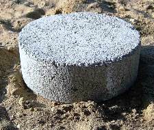 The builder insists upon digging the holes with the 12-inch diameter auger he has mounted on the back of his farm tractor. He refuses to set the posts in concrete, because if he doesn’t get a post in the right place, he wants to be able to move it around in the hole. His idea is to dig a four foot deep hole, and drop 12-inch diameter concrete cookies in the bottom of the hole!