For some obscure reason people planning new buildings tend to scrimp on height. In most instances, designing a new fully engineered post frame building – whether for a barndominium, shop house (shouse), garage, shop, etc., just a little bit taller is a relatively inexpensive proposition and can save many more dollars and mental anguish than having to alter after construction.
Reader CHRIS in SNOHOMISH writes:
“I have a pole barn with a center door for Rv, above is an additional living space, the width is 12’6” depth of 41’ height of 13’, I need to shorten the truss’s so I can gain 6” height , current truss are HY floor joists, question is can I put 2×6” spaced every 8”’s and have the same weight carrying capacity?”
Mike the Pole Barn Guru writes:
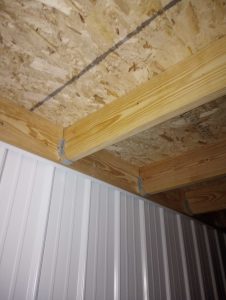 HY floor joists are wood prefabricated I joists. Let’s take a look at Chris’ proposed design solution (please keep in mind, any structural design solution should be reviewed by your building’s engineer to confirm structural adequacy):
FLOOR JOIST DESIGN
Assumptions:
Joist span 12.5-ft.
joist spacing = 8″ o.c.
joist live load = 40 psf
joist_dead_load = 10 psf
Fb: allowable bending pressure
Fb‘ = Fb * CD * CM * Ct * CL * CF * Cfu * Ci * Cr
CD: load duration factor
CD = 1 NDS 2.3.2
CM: wet service factor
CM = 1 because floor joists are protected from moisture by roof
Ct: temperature factor
Ct = 1 NDS 2.3.3
CL: beam stability factor
CL = 1 NDS 4.4.1
CF: size factor
CF = 1.3 NDS Supplement table 4A
Cfu: flat use factor
Cfu = 1 NDS Supplement table 4A
Ci: incising factor
Ci = 1 NDS 4.3.8
Cr: repetitive member factor
Cr = 1.15 NDS 4.3.9
Fb = 900 psi NDS Supplement Table 4-A
Fb‘ = 900 psi * 1 * 1 * 1 * 1 * 1.3 * 1 * 1 * 1.15
Fb‘ = 1345.5 psi
fb: bending stress from live/dead loads
fb = live + dead load * joist spacing / 12 / 12 * (sf * 12 – 1.5)2 / 8 / (b * d2 / 6)
fb = 50 psf * 8″ / 12 in./ft. / 12 in./ft. * (12.5′ * 12 in./ft. – 1.5″)2 / 8 / (1.5″ * 5.5″2 / 6)
fb = 1012.5 psi <= 1345.5 psi so okay in bending
Δallow: allowable deflection
Δallow = sf * 12 / 360 IBC 1604.3
Δallow = 12.5′ * 12 in./ft. / 360
Δallow = 0.4167″
Δmax: maximum deflection
Δmax = 5 * live load * joist spacing / 12 / 12 * (sf * 12 – 1.5)4 / 384 / 1600000 / b / d3 * 12 from http://www.awc.org/pdf/DA6-BeamFormulas.pdf p.4
Δmax = 5 * 40 psf * 8″ / 12 in./ft. / 12 in./ft. * (12.5′ * 12 in./ft. – 1.5)4 / 384 / 1600000 / 1.5″ / 5.5″3 * 12
Δmax = 0.423″ > 0.4167:
∴2×6 #2 DougFir joists will not work at 8″ on center due to not meeting deflection criteria
Chris’ options are to buy #1 or Select Structural graded 2×6 DougFir or go to 6″ on center spacing.
 I have developed a professional respect for a builder based in Northern Idaho. Recently I visited his website and saw some photographs leading me to ask about how he solves “barn style” wall girt design issues. He was right on top of it – his photos were of older buildings and he switched to all bookshelf style wall girts years ago, I applaud him for doing so!


