I am asking for feedback from RDP’s and Building Officials because:
There is a method to my madness. Seriously. I want to make sure we are doing things 100% correctly. In my humble opinion there are currently numerous post frame buildings being constructed where wall girts do not meet Code or acceptable engineering practice.
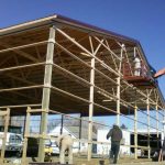 I have developed a professional respect for a builder based in Northern Idaho. Recently I visited his website and saw some photographs leading me to ask about how he solves “barn style” wall girt design issues. He was right on top of it – his photos were of older buildings and he switched to all bookshelf style wall girts years ago, I applaud him for doing so!
Lots of architects, engineers and building officials read my articles, thank you! Your wisdom is appreciated. Attached is an example set of wall girt calculations. If there is an error in any direction, or something missed, your feedback would be more than appreciated. Thank you in advance.
Code is 2015 IBC (International Building Code)
Building Summary
| Building Footprint Width | 40′ |
| Building Footprint Length | 60′ |
| Building Footprint Height | 17′ |
| Square Footage (area contained by embedded poles) | 2400 ft2 |
| Total Roof Area | 2745 ft2 |
| Total Wall Area | 3191 ft2 |
| Building Eave Height | 17′ |
| Roof Style | GABLE |
| Slope | 4/12 |
| Roof Height | 20.33′ |
| Building Conditioned | Yes |
Wind Summary
| Vult | 110 mph |
| Vasd | 85 mph |
| Risk Category | I |
| Wind Exposure | B |
| Applicable Internal Pressure Coefficient | 0.18 |
| Components and Cladding Design Wind Pressure | |
| Zone 1 | -19.78 |
| Zone 2 | -32.985 |
| Zone 3 | -49.217 |
| Zone 4 | -23.522 |
| Zone 5 | -27.936 |
| Zone 1 Positive | 11.826 |
| Zone 2 Positive | 11.826 |
| Zone 3 Positive | 11.826 |
| Zone 4 Positive | 21.188 |
| Zone 5 Positive | 21.188 |
| Duration of Load for Wind | 1.6 |
| Structure type | Enclosed |
wall girt size: 2″X6″
spacing between girts = 22.5″
girt span = 139.875″
supported by 2×4 blocking every 139.875″
Fb: allowable girt pressure
Fb‘ = Fb * CD * CM * Ct * CL * CF * Cfu * Ci * Cr NDS 4.3
CD: load duration factor
CD = 1.6 NDS 4.3
CM: wet service factor
CM = 1 because girts are protected from moisture by building envelope
Ct: temperature factor
Ct = 1 NDS 4.3
Cfu: flat use factor
Cfu = 1 NDS 4.3
Ci: incising factor
Ci = 1 NDS 4.3
Emin: reference adjusted modulus of elasticity
Emin = 470000 psi NDS Supplement
Cr: repetitive member factor
Cr = 1.15 NDS 4.3
lu: laterally unsupported span length
lu = 139.875″
le: effective length
le = 1.63 * lu NDS table 3.3.3
le = 244.496″
CF: size factor
CF = 1.3 NDS 4.3
CL: beam stability factor
CL = 1 NDS 3.3.3
Fb‘ = 850 psi * 1.6 * 1 * 1 * 1 * 1.3 * 1 * 1 * 1.15
Fb‘ = 2033.2 psi
fb: girt test pressure
fb = 6 * 0.6wall_wind_force / 144 * girtSpacing * span2 / 8 / (b * d2) NDS 3.3
fb = 6 * 17.389 psf / 144 in.2/ft.2 * 24″ * 139.875″2 / 8 / (1.5″ * 5.5″2)
fb = 937.255 psi
937.255 ≤ 2033.2 stressed to 46% ∴ 6″X2″ #2 OK in bending
Fv‘: allowable shear pressure
Fv = 135 NDS Supplement Table 4-A
Fv‘ = Fv * CD * CM * Ct * Ci NDS 4.3
Fv‘ = 135 psi * 1.6 * 1 * 1 * 1
Fv‘ = 216 psi NDS Supplement
fv: shear girt pressure
fv = 3 * (0.6wall_wind_force / 144 * girtSpacing * span / 2) / (2 * b * d) NDS 3.4
fv = 3 * (17.389 psf / 144 in.2/ft.2 * 24″ * 139.875″ / 2) / (2 * 1.5″ * 5.5″)
fv = 36.854 psi
36.854 ≤ 216 stressed to 17% ∴ 6″X2″ #2 OK in shear
Deflection
Δallow: allowable deflection
l = 139.875″
Δallow = 139.875″ / 90
Δallow = 1.5542″
Δmax: maximum deflection
Δmax = 5 * 0.6W * spacing * span4 / 384 / E / I from http://www.awc.org/pdf/DA6-BeamFormulas.pdf p.4
E: Modulus of Elasticity
E = 1300000 psi NDS Supplement
I: moment of inertia
I = b * d3 / 12
I = 1.5″ * 5.5″3 / 12
I = 20.796875 in.4
Δmax = 5 * 12.173 psf / 144 psi/psf * 24″ * 139.875″4 / 384 / 1300000 psi / 20.796875 in.4 components and cladding reduced by .7 per footnote f of IBC table 1604.3
Δmax = 0.37401″ ≤ 1.5542″


