Tag Archives: engineer of record

Getting the Best Deal on Your New Post Frame Building

A price quote is merely a number without a complete understanding of exactly what is or is not included in said quote.

You have requested quotes for your new post frame building from a dozen or more providers and actually gotten four back, even after having to hound all of them for pricing! Frustrating when you are ‘knocking at their door’ trying to spend your cash.

One quote stood out above all others with an exceptional price, so you place your order. Only after “everything” arrives and you try to assemble it do you find out what you thought you bought and what you really purchased are not quite equal.

Disappointing.

If you prefer to read books by starting with the last chapter, you can skip to there to find a solution.

Here are a few points to be aware of:

Will Your Building Meet Minimum Building Code Standards?

Those quotes you got….few, if any, will specify what loads your building are designed for.

Some of them will just be a list of materials! Are they right? Is there even enough there to construct a building?

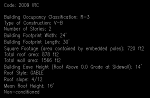
Every quote should include (at a minimum): engineer sealed plans specific to your building at your site. Complete Building Code information – including Code version (there is a new one every three years), Ground snow load (Pg), Flat roof snow load (Pf), Design wind speed (Vult or Vasd), Wind Exposure (there is a big difference between Exposure B and C) and assumed soil bearing pressures.

You can easily acquire this information for yourself, so you have a point to check from: https://www.hansenpolebuildings.com/2019/01/building-department-checklist-2019-part-1/

If Code information is not on a quote, chuck it.

Do Roof Trusses Quoted Meet Your Needs?

Here is where investing in an engineered building comes into play, as your Engineer of Record (person who seals your building plans) should be reviewing prefabricated roof truss drawings for their adequacy for his or her building.

Planning on supporting a ceiling, either now or at a later date? If so a ceiling load of no less than five pounds per square foot (psf) should be indicated on engineered plans as well as a BCDL (Bottom Chord Dead Load) to match on sealed truss drawings.

At Hansen Pole Buildings, we ran into this situation so often, we decided to upgrade all trusses up to 40 foot clearspan to support a minimum five psf load.


How is Roof Steel Condensation Being Controlled? Most providers are not even going to mention this. Most of us prefer it not to rain inside of our new buildings. 

I answer questions online every Monday. Problem/question number one is regarding condensation.

From cheapest up – a Radiant Reflective Barrier (aka bubble wrap – if going this route you only need single bubble, six foot wide rolls with an adhesive pull strip); Integral Condensation Control (https://www.hansenpolebuildings.com/2017/03/integral-condensation-control/); Sheathing with 30# felt; Closed cell spray foam.

Planning on insulating and finishing walls? If not using closed cell spray foam you will want to apply a Weather Resistant Barrier between wall framing and steel siding.

What Written Warranty Comes With Your Building?

If it does, how long does it last? What does it include? When it comes to Post Frame Building kits, Hansen Pole Buildings stands alone with a Limited Lifetime Structural Warranty (https://www.hansenpolebuildings.com/2015/11/pole-building-warranty/).

Are Assembly Instructions Included?

If not, there is plenty left to chance. Hansen Pole Buildings provides a fully illustrated, step-by-step 500 page Construction Manual. And, if you get stuck, there is unlimited FREE Technical Support from people who have actually assembled buildings!


How About Your Potential Provider?

How long have they been in business 2 years, 5 years? How about 18 years? How many post frame buildings have they provided? How about roughly 20 thousand buildings located in ALL 50 states!

Here is how to vet any potential provider: https://www.hansenpolebuildings.com/2015/01/pole-building-suppliers/

I promised you a solution (aka Last Chapter of Book)

We are offering to shop for you.  Seriously? Yes! You provide up to three names of competitors to Hansen Buildings, where you can purchase a complete wood framed post frame building kit package, and we will shop them to get quotes for you.

Now we say three, because frankly, some people just are not very prompt or cooperative when it comes to getting back with price quotes.

Why would we do this?  Comparing “apples to apples”, we know our price will beat theirs, every single time. We offer to do this for your peace of mind.   We guarantee all other prices will be higher.  And we will provide you with documentation to prove it!

There is a catch…..before we go shopping you have to place your order for your new Hansen Pole Building kit….. subject to us “proving our point” by going shopping. Your payment to us will not be processed for ten calendar days. Within seven days of order, you’ll have competitive quotes in hand, or our documentation of having hounded them every week day for a week trying to get pricing for you (seriously, if you have to hound someone for a price, what kind of after sale service will you get?). 

After we email you proof, if you seriously want to purchase from one of these competitors, just let us know before ten days pass and we tear everything up and go away friends.

Building Near Nashville, Engineered Plans, and Clear Spans

Today the PBG answers questions about building near Nashville, engineered plans for a possible client, and the possible clear span of trusses.

DEAR POLE BARN GURU: Can we have this built near Nashville TN? CRAIG in SAN CLEMENTE

Nashville Tennessee on a map


DEAR CRAIG: We can provide a new Hansen Pole Building kit package anywhere in the United States.


DEAR POLE BARN GURU: Hello, We are interested in one of your barn plans for purchase. We will need engineered plans to submit to our local county development team for gaining approval and permits. Can we get the engineered plans first? TINA in SNOHOMISH

DEAR TINA: Thank you for your interest in a new Hansen Pole Building. You will need to complete a building department questionnaire which provides us the necessary load information we need to properly design your structure, with that we guarantee our third-party engineered plans will pass a structural approval. Usually your plans will be sent to you in seven to 10 days after you have electronically approved your documents.


DEAR POLE BARN GURU: What is the greatest clear span available? KEITH in NEWARK

DEAR KEITH: In most geographic areas 80 foot, however there are some parts of the country where we can provide as wide as 100 feet.


.


Ever Wonder What a Post Frame Engineer Does? Part I

I have been pooh-poohed on occasion for my insistence every post frame building (or barndominium) should have an engineer involved. Very few potential building owners understand what it is an engineer does or how they are adding value to a particular project. 

To follow, in its entirety, is an article by Jess Lohse, originally published in SBC Magazine, June 10, 2019. Once read, you should (like me) go away wondering how it is engineers work as reasonably as they do.

Structural engineers, often referred to as an Engineer of Record (EOR), are positioned early in the construction design process ensure the structural viability of buildings designed by Architects or Building Designers. Certain buildings are exempted from the legal requirements for the use of an Architect or Engineer. Generally these buildings are designated as 1 and 2 family residential structures designed within the prescriptive code. Buildings designed under the IBC, exceeding certain provisions of the IRC or exceeding legal exemption requirements will employ the use of an EOR. Structural engineers are typically brought into a project by the architect/building designer and work on behalf of the project owner and remain engaged throughout the construction of a structure to review and accept deferred submittals and RFIs (request for information) for conformance with the structural plans and specifications, monitor construction and perform special inspections as defined on the permit or as contracted to undertake. Once engaged on a project an EOR will typically work through the following processes:

  1. Conceptual Design
  2. System Design
  3. Element Engineering
  4. Iterative Design & Drafting
  5. Construction Administration

Conceptual Design

  • Review Arch drawings
    • Unit types
    • Bearing walls stack?
  • Location requirements
    • Soil report
    • Exposure Category
    • Wind Load
    • Seismic Load
  • Initial design of building elements
    • Roof, wall & floor layout per Arch drawings
    • Footings & Slabs
    • Bearing walls, Beams & Columns
    • Review MEP conflicts

Conceptual Design

An initial step a structural engineer will take is to review the drawings produced by the architect/building designer. The engineer will look at the various types of units on a larger multifamily project or the variety of room uses in a larger single family home or commercial structure to have an idea of the various uses of a structure. Consideration will be given to potential bearing walls, obviously inclusive of the exterior walls, but potentially to utilize interior walls should the need arise to distribute loads through the interior of the structure.  If the structure has multiple levels, the engineer will note if interior walls fall on top of each other, commonly referred to as ‘stacking’, to efficiently transfer loads between levels.  This information will be referred back to the architect to make any necessary adjustments.

The EOR will determine site specific requirements for the structure that are dependent on its location. This will include a soil report to determine potential footings, which exposure category to design to, applicable wind loads as well as seismic considerations. Once the environmental factors have been determined, the engineer will perform an initial design of building elements such as roof, wall and floor layouts per the architectural drawings, footings and/or slabs, bearing walls including beams and columns, and identify potential mechanical, electrical, and plumbing conflicts. 

Come back tomorrow for a continuation of what an EOR, Engineer of Record, adds to the design and scope of a post frame building.

Adding a Second Floor to an Existing Pole Building

Adding a Second Floor in an Existing Pole Building

second floorMore than one pole (post frame) building owner has an idea of adding a second floor inside their existing building. Or, they plan a new post frame building with an idea of a future second floor being incorporated.

This apparently simple proposition has no simplicity involved.

Reader RYAN in HAMPSTEAD writes:

“Good morning,I have a 30×40 pole building, and I’m looking to add a partial second floor.  The posts are 8x8s, set at 8′ OC.  I’ve attached a layout for trusses that I received from another vendor, based on specs I provided.  The exact indoor measurement is about 29’11” outside to outside of the 8x8s (to the exterior sheeting).  The distance between the posts is about 28’6″.  So the joists should be field trimmable or around 29’8″ to carry from ledger to ledger.  I do not currently have the ledger/ribbon boards purchased or installed.

The trusses will be clear span, and the total floor space will be 30’x24′ with a cutout for a staircase.  Can you send a quote for this?  The shipping zip is 21074.

Thanks.”

Mike the Pole Barn Guru Writes:

Hansen Pole Buildings does not manufacture trusses, so we weren’t able to solve this portion of Ryan’s challenge. However, there are some considerations anyone should consider when looking towards a second floor being inserted in an existing post frame building.

Before moving forward, an EOR (Engineer of Record) should have originally designed your building. This person should be consulted with, as a second floor places a tremendous load upon wall columns and may overload footings (not to mention columns themselves), possibly causing columns to sink. Headers (also known as ledgers/ribbon boards) as well as attachment of floor trusses to them also need to be engineer designed. If somehow an engineer did not design your building, a competent one should be engaged to verify adequacy or design a repair.

Don’t be pennywise and pound foolish when it comes to structural changes involving a second floor, mezzanine or loft – lives you save may be your own, or those of a loved one!


Advice on a Hay Barns, and Registered Design Professionals (Use them)!

Today Mike advises on the Post Frame construction of Roof Only Hay Barns, and the need to use a Registered Design Professional.

DEAR POLE BARN GURU: You have a page showing roof only hay barns. There are two photos, one which shows a partially enclosed hay barn. I am very interested in this for my ranch…..what are its dimensions? I will need full walls along three sides, and a partial wall, like the one you show in the photo along the front side. DAVE in PETALUMA

About Hansen BuildingsDEAR DAVE: Rather than working off from the dimensions of a building which best fit some prior client’s wants and needs, you will be far better ahead to work with one of the Hansen Pole Buildings’ Designers to come up with the dimensions and features which will best fit with your budget. If you can do a design which has some or all of both of the narrow (peaked) endwalls enclosed from roofline to the ground, it will normally be the most cost effective.


DEAR POLE BARN GURU: What diameter holes do I dig for my post when my barn is 44’x32’? Trusses are spanning the 44’ way. TERRY in COLUMBIA CITY

DEAR TERRY: The Registered Design Professional (RDP – architect or engineer) who designed your building and sealed the plans for you will have called out the depth and diameter of the column holes as well as concrete footing and encasement requirements.

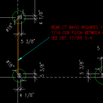
He or she takes into account all of the climactic loads placed upon your building – wind, snow and seismic, along with the allowable soil bearing capacity of your site in making the determination. The other factors they will have taken into account include the spacing of the columns, eave height, roof slope as well as the dead loads the building must support (not only the weight of the building as proposed to be constructed, but also future loads such as wall and ceiling finishes).

If by some chance you do not have a RDP involved in your project – go hire one now, it is money well spent. Or, better yet, invest in an engineered post frame building kit package which will come with complete plans.


DEAR POLE BARN GURU: We are building a pole barn but have decided to use timber frame scissor trusses in the open area where the trusses will be visible. Three trusses, made from 8×10 timbers will be in a area that is fully open. The other 3 trusses will be prefab, “regular”, as they will not be visible (one inside interior wall and other 2 at gable ends.
I’m having trouble finding a way to attach the purlins to the timbers in a way that the will not have exposed Simpson seismic and hurricane hangers. There must be a hanger that can be used with ‘simple’ blocking that will attach the purlins to the top of the timbers and still create a look as if the purlins are simply resting on the timbers.
Any ideas?
Thanks in advance for your advice! FAITH in SALEM

Engineer sealed pole barn
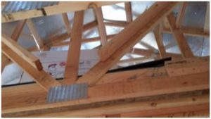
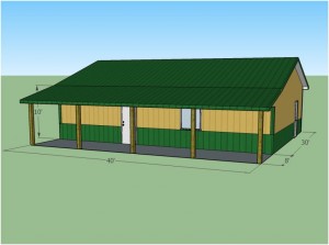
DEAR FAITH: This is a question which is best posed to the RDP (Registered Design Professional – architect or engineer) who designed your building and provided the sealed blueprints for you to build from. I am not aware of an engineered hanger which will do what you are looking to accomplish, however there may be a direction in which to head for a solution. By predrilling holes through the purlins from narrow edge to narrow edge, it might be possible to utilize a number of very long spikes or drive screws which could provide the needed resistance to uplift and seismic forces. In order to have adequate area for connectors, it might take going to a three or four inch wide purlin, which may turn out to work well aesthetically with your timber framed trusses. There will need to be blocking placed on top of the trusses, between the purlins to prevent rotation.


Structural Engineering

I’ll take Structural Engineering for $XXX Alex

Proper Engineering in post frame construction can not be overlooked.

Alex Trebek has hosted Jeopardy!, the iconic daily syndicated game show, since 1984. With over 7,000 episodes aired, Jeopardy! has won a record 33 Daytime Emmy Awards. Some of you may even have tuned in for an episode or three.

Today’s Answer Is:

Insufficient Data to Provide an Answer

And reader PAUL from FINKSBURG has the question:

“What size header would be required for a 20′ wide overhead garage door placed on the truss bearing wall?”

Okay, enough of my being snarky. The answer to Paul’s question should be clearly indicated on the engineer sealed plans for his building, along with the required connections from truss to header and header to columns.

If somehow the engineer of record overlooked this critical element, he or she should be contacted immediately to provide the missing data. Even worse – maybe an engineer happened to not design the building, in which case CALL ONE NOW.

Whilst this may appear, on the surface to be a simple question, there are a plethora of factors which go into the determination of a structural header to carry roof loads. This would include, but are not limited to:

Pg – the Ground Snow Load

Ce – the Snow Exposure Factor (sites which are open to the wind allow snow to blow off the roof, sites which are protected from the wind keep snow on the roof)

Is – the Snow Load Importance Factor (Risk Category I buildings are a lower hazard to human life, therefore the flat-roof snow load will be reduced)

Ct – the Thermal Factor (heated buildings melt snow off, unheated buildings allow snow to build up)

Pg, Ce, Is and Ct are multiplied together along with 0.7 to determine the Flat-Roof Snow Load (Pf)

But wait, there is more…..

Pf might be further reduced depending upon the roofing material (steel roofing being slick allows snow to slide off quicker), whether or not snow retention systems are present (which hold snow on the roof), as well as the roof slope. Mix them all together and the Sloped Roof Snow Load (Ps) is created.

The dead loads imposed upon the roof also need to be added to the mix – the weights of trusses or rafters, purlins, roof sheathing, insulation supported by the roof system, roofing, truss bracing, ceilings are amongst some of the weighty culprits.

Once all of these contributing factors are combined into a psf (pounds-per-square foot) load, concentrated loads are applied to each of the truss bearing locations along the header – these are based upon ½ of the truss span (including any sidewall overhangs) multiplied by the truss spacing and the applied loads.

Not only does the header need to be verified for adequacy in load carrying capacity, but also limited in deflection. A sagging header can cause unsightly rooflines as well as preventing doors from operating correctly.

Self-engineering is not a good choice – call your engineer….now!

Problems in Steel Truss Building Land

Problems in Steel Truss Building Land

Disclaimer – Hansen Pole Buildings does not provide steel truss post frame buildings and I have never personally been involved in the structural design of one, however there are a plethora of readily evident challenges with this building which should be properly addressed.

Reader JAMES in TALLAHASSEE writes:
“I am framing in three sections of a five section clear span metal truss barn. In addition to the roof purlins on top of each truss there is a row of 2×6 lateral bracing running through the web of the truss. Can I remove the two that would be running directly through my framed wall? It’s not vertical but angled toward the peak so framing and siding around it will be trial and error. I even considered pulling it and using a steel cable to replace it. The ones I am speaking about are over each window in the picture but it is the opposite wall I am concerned about.” Mike the Pole Barn Guru writes
James ~

I will address your question first, then will share some challenges I see with your building – many of which should be addressed to the engineer of record (EOR) who sealed the plans for your building.

It is unlikely you would be able to safely structurally remove the braces, they keep the bottom chord of the truss members from bucking in the weak direction (towards the endwalls) under stress reversals caused by high wind loads. It might be possible to cut them and anchor them into each side of your interior framed wall, provided the wall is adequate to support the imposed loads. This is a question which would need to be posed to the EOR. AS for replacing the lumber braces with steel cable – not going to work. The cable would be strong in tension, however offers no resistance to compression. If the cables were to be placed in an X fashion (going from top of one truss to bottom of the next, as well as bottom to top) it might be possible, however again poses engineering and connection challenges which should be addressed by the EOR.

Moving on to some structural problems I see with your building (again all of these should be addressed directly to your EOR as he or she has placed their seal on the plans and have ultimate structural responsibility)….

As best I can tell, the columns and steel truss frames of your building are placed every 12 feet. If they are over 10 feet apart, a single 2x member as bottom chord bracing is inadequate – under load they will buckle in the weak direction. Solutions could include – adding a 2×4 to the top or bottom of the 2×6 to form either a T or an L. Typical attachment would be with a 10d common nail, generally at 12 inches on center.

It appears your building has 12 foot sidewalls, if so engineering is required to design the size and spacing of the studs in your walls. You have a serious problem in your endwalls – code requires the studs to run from the bottom plate to the roof line continuously. In your instance, a hinge point has been created at the plate line running across the endwall at eave height. Without some serious engineering analysis to brace this point, your endwalls will buckle at this point under windloads – generally being sucked outward.

I am also seeing “air” between the roof purlins where they cross the endwall truss. In order to adequately transfer the wind shear loads from the roof to the endwalls – solid blocking is required between the purlins at the endwall.

In the event an engineer was not involved in the original design of your building, I cannot recommend strongly enough for you to hire a local Registered Design Professional (engineer or architect) who can physically visit your building and provide structural solutions for the challenges visible in your photo, as well as others which may not be readily evident from our limited viewpoint. I am not trying to get you to spend your hard earned dollars for naught, I would just like to make sure your building stays upright in the next wind event.

The Contractor Factor! When Plans Go Awry!

The Contractor Factor

I hear too many stories where well-intentioned folks hire a contractor to erect a pole barn (post frame building) and end up with less than they bargained for.

This is avoidable, with an ounce of prevention.

Reader DONNA in REMSEN writes:


“I had a pole barn put up in Sept this year, contract said contractor would fill area with gravel to raise the grade as it was being built on a slope. So instead the builder just dumped 4 loads of sand on top of the grass, pushed it around with a bobcat till fairly level, and built the pole barn on top. I live in an area that calls for pole to be 4 feet in virgin soil, the builder put some down 2 feet, in the sand and some 3 feet, in the sand. Now the whole thing has huge pits around the poles and the doors won’t shut any longer, it’s been a month!! Builder says it is normal. I am afraid of what else it will do with the posts not down too deep, any suggestions.”


Hopefully you have not paid the builder. It sounds like you have a plethora of potential challenges going on. This is the order in which I would address them:

First – contact the Building Inspector who signed off on the building inspections. He or she should be asked to prepare a list of corrections which must be completed in order to obtain an occupancy permit.

Second – have the Engineer of Record who sealed the original building plans do a field inspection of the building and prepare a list of deficiencies which need to be corrected.

Third – take the two lists from above and the contract between you and your contractor to an attorney who specializes in construction law. The attorney can then prepare the appropriate documents to be sent to the contractor giving the builder a set time frame (which may be spelled out in the contract documents) in which to correct the deficiencies.

There is a strong possibility the contractor will ignore your attorney, hopefully the contractor has sufficient assets for you to attach in the event you are the prevailing party in legal action. This is one of the reasons I strongly encourage anyone who is hiring a building contractor to require the posting of a performance bond as a guarantee the work to be performed is actually completed in accordance with the contract documents.

More about contractor bonding can be read here: https://www.hansenpolebuildings.com/2012/07/contractor-bonding/.


Converting a Pole Barn to a Residence

Reader BAILEE in LARAMIE writes:

“Hi, I have a few questions about the structure of turning a pole barn to a residence in the Laramie, Wyoming area. The current project I am working on has pole spacing of about 10-12 feet. I wanted to know if this is still structurally stable with traditional framing with the wind in Wyoming? If not, would it be wise to double the sidewall girts for more support within the walls? Also, if we were to use the traditional framing with 8 foot spacing would that be stable?

Next, do you have any window diagrams that detail the insulation and wall construction within residential pole barns that your company would be able to share?

Please let me know. Thanks for any help that you can provide.”

Mike the Pole Barn Guru Answers:

As to the structural stability of any post frame building, anywhere – it depends upon the climactic conditions to which the building was designed by its engineer of record (EOR). If this is an existing building, you may have some challenges, as most “pole barns” are at best designed as Risk Category I buildings – which pose little or no threat to human life in the event of a catastrophic situation. Residential buildings are to be designed to Risk Category II, which increases the needed design wind and snow loads.

In the event you are installing an interior finish other than steel liner panels (most folks sort of enjoy gypsum wallboard taped and textured) members which support these types of finishes need to be designed for far less deflection. Back to in the event this is an existing building – the EOR should be consulted to determine which members need to be upgraded to meet with your now intended use of the building. Under no circumstance attempt to do this without the consultation of an EOR, it is not worth risking the wellbeing of yourself or your loved ones.


If you are starting from scratch – invest in a building kit package which has been designed by a registered design professional (architect or engineer) who has clearly been advised as to your intended use of the building. The plans they provide will call out all of the members and framing details necessary to give you an end resultant which you and the generations which follow you can enjoy.


For a small nominal fee, you can invest in a Hansen Pole Buildings’ Construction Guide, the price of which can be credited towards your purchase of one of our complete post frame building kits. Contact Bonnie@HansenPoleBuildings.com if this is of interest to you.

Truss Bracing- A Framer’s Perspective

Truss Bracing
My friend Christopher Gould is a Registered Professional Engineer and President of Gould Design, Inc (https://www.goulddesigninc.com/). He recently authored a blog article on truss bracing, of which I will steal (borrow) profusely from him.

Truss bracing is additional, field installed, bracing which is specified by the design software to reinforce specific webs needing extra support to meet the loading and design requirements of the job.

What we are referring to are web braces which are typically displayed as the symbol shown below:

truss-web-bracing

A system of trusses may also require additional “bracing” specified by the EOR (Engineer of Record) such as gable bracing like this:

gable-truss-bracing

These details are typically found in the structural plans, and as a framer are the easiest details to find and install, since they are related to nailing requirements and necessary hardware and clips which should be installed on order to satisfy shear transfer and drag loads. These are also the easiest pieces of reference for the building inspector to identify.

Bright, shiny clips and straps have a way of standing out against wood on a job site. Much more so than additional wood on top of the many directions of webs in a truss system like this:

truss-plate

These pesky braces tend to be the most misunderstood and overlooked part of installing a truss system when it comes to completing a job, especially if the crew doing the work and the building inspector don’t know what they are looking for. When the trusses are delivered they leave behind a packet of paper which can be hundreds of pages with a layout on top. The layout is often peeled off and used for proper placement of the various trusses, but the rest of the packet showing the truss profiles and required web bracing is tossed aside and possibly not looked at again.

Many times flipping a web or upgrading the web lumber can eliminate many of the braces which are specified through system default design without the designer spending much time on it.

This last step is part of what Hansen Pole Buildings’ beloved Purchasing Department Manager (and newlywed) Justine does. When she gets a preliminary truss drawing in from our truss manufacturer, she reviews the required web bracing and consults with the truss designers to see if there is a solution which will reduce or eliminate the need for web bracing. While this may add a few dollars to the cost of the trusses, it can well result in a wash for cost by reduction of bracing – and make it easier for you to construct your new pole building!

When the average person or builder invests in a set of roof trusses, often the dictate for selection is low price of the trusses, without looking at the added costs of bracing which another fabricator might have very well taken into account.

Just one more reason to invest in a post frame building kit package from the people who deliver “The Ultimate Post Frame Experience”™.

Pole Building Truss Framing

My Truss Framing Does Not Match the Plans

Every good set of pole building plans should have at least one page upon which is drawn a “cut through” view or cross section of the building. To read about what should be depicted on this page: https://www.hansenpolebuildings.com/blog/2011/10/pole-building-plans-101-interior-section-elevation/ or actually view an example at: https://www.hansenpolebuildings.com/sample-plans.htm.

sample building plans
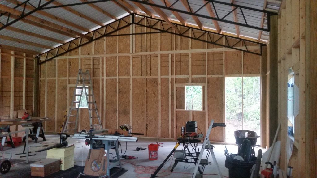
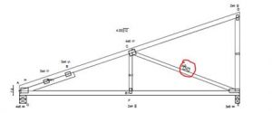
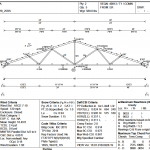
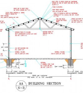
One of the features of this page, for buildings utilizing prefabricated roof trusses, is a generic representation of the roof trusses. The trusses will be shown accurately for span (the length of the truss from outside of column to outside of column) as well as roof slope. Any lateral (the length direction of the building – perpendicular to the trusses) permanent bracing for the truss top chords (the roof purlins) as well as the bottom chords which are required by the Engineer of Record, will also be depicted on this drawing.

As the person doing the drafting is not privy to the final trusses drawings, provided by the roof truss fabricator, at the time the plans are drawn, truss members on the plans will not resemble those of the actual delivered trusses.

What things might be different? Everything!

The sizes of any and all members could very well be different than drawn. As well, the configuration (or pattern) of interior truss members (webs) will most likely not even be close.

Do not fret – they are not meant to be a match.

An often confusing part of the sealed truss drawings from the manufacturer, may be what is shown as top chord bracing. Many times what appears on the drawings as a 2×4 placed flat over the top of the truss, is merely the truss engineer’s showing the recommendation for the truss to be braced. The Engineer of Record is responsible for permanent truss bracing design, which is typically accomplished by the roof purlins being placed on edge between the trusses.

Breathe deep, exhale completely and move forward following the truss framing installation instructions, and everything will be just fine!

Letter From a Building Official

A fair number of Building Officials are readers of my blog. This is not meant to offend any, but is an example of what pole building providers are faced with on a regular basis.  The following is a letter to one of our clients:

“Mr. Fxxxxxx,

This is the list items that need to be addressed;

  1. The footings supporting the “Girder Loads” (any footing with the truss bearing on the posts) will need to be 24” wide x 12” deep at a minimum of 30” below grade. Any footing supporting a “non-point load or concentrated load” will need to be a minimum of 18” in width.
  2. The posts cannot be “encased” in concrete footing.
  3.  The proposed Roof Trusses “Girder Trusses” will need to be certified by a Professional Engineer registered in the State of Maryland. I will need a copy of the sealed drawings for our file and a copy will need to be at the job site during the framing inspection as well.
  4. The use of “Ledger Locks” has not been approved by our jurisdiction for use in Pole Buildings. You will need to use 2 pcs. (min) ½” carriage bolts at each post to Girder/Beam connection.
  5. The concrete slab cannot be tied into the posts as specified on the building plans. The posts must be isolated from the concrete slab by use of a minimum ½” expansion joint.

You may want to forward this info to the Pole Barn Company so they can make any changes to your plans.”

To begin with, the Building Official is now putting himself in the position of being “Engineer of Record”, as he is spelling out how he wants the building to be constructed. Chances are the county attorney would not be pleased by his taking on this liability.

Jumping past opening up this can of worms….as far as we can find from our research there is no justification for a footing of 24 inch width, having to be 12 inches in depth. One engineer’s table we found online, does not specify a 12 inch thick concrete pad footing for a column – until the footing would be supporting 48 kips (a kip is 1,000 pounds of force) and be 6 feet in diameter!

The posts cannot be “encased” in concrete footing? I hate to point out 1805.7.3 of the International Building Code (IBC)….which directly contradicts this Building Official statement.

Number three on the list – a non-issue.

Plans Examiner seems to be “stepping out” a little on this one. “Ledger Locks” happen to have an ICC-ES approval number (#1078). With proven published values, as well as International Building Code approval….he’s not looking good on this one. Assuming both the truss and the column were Southern Pine, those ½” bolts are good for only about 350# of resistance each.

Now we will get to “the posts must be isolated from the concrete slab”. IBC 1805.7.2.2 has the formula for the embedment of a constrained column…”where constraint is provided at the ground surface, such as a rigid floor or pavement”. The National Frame Builders Association “Post-Frame Building Design Manual” in Section 8.2.2 specifies, “An example of a constrained post foundation would be when the post is installed immediately adjacent to a concrete slab floor in the building”.

The client ends up being faced with either complying with these ridiculous requirements or paying for an engineer to fight the battle. This, in my humble opinion, is a public servant, who is not serving the public.