Problems in Steel Truss Building Land
Disclaimer – Hansen Pole Buildings does not provide steel truss post frame buildings and I have never personally been involved in the structural design of one, however there are a plethora of readily evident challenges with this building which should be properly addressed.
Reader JAMES in TALLAHASSEE writes:
“I am framing in three sections of a five section clear span metal truss barn. In addition to the roof purlins on top of each truss there is a row of 2×6 lateral bracing running through the web of the truss. Can I remove the two that would be running directly through my framed wall? It’s not vertical but angled toward the peak so framing and siding around it will be trial and error. I even considered pulling it and using a steel cable to replace it. The ones I am speaking about are over each window in the picture but it is the opposite wall I am concerned about.” 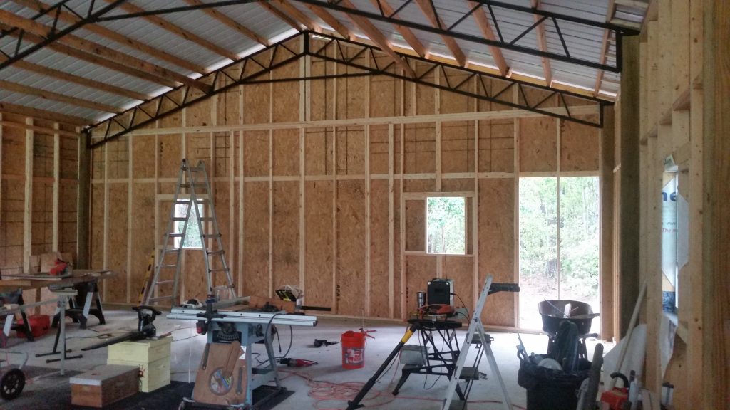 Mike the Pole Barn Guru writes
James ~
I will address your question first, then will share some challenges I see with your building – many of which should be addressed to the engineer of record (EOR) who sealed the plans for your building.
It is unlikely you would be able to safely structurally remove the braces, they keep the bottom chord of the truss members from bucking in the weak direction (towards the endwalls) under stress reversals caused by high wind loads. It might be possible to cut them and anchor them into each side of your interior framed wall, provided the wall is adequate to support the imposed loads. This is a question which would need to be posed to the EOR. AS for replacing the lumber braces with steel cable – not going to work. The cable would be strong in tension, however offers no resistance to compression. If the cables were to be placed in an X fashion (going from top of one truss to bottom of the next, as well as bottom to top) it might be possible, however again poses engineering and connection challenges which should be addressed by the EOR.
Moving on to some structural problems I see with your building (again all of these should be addressed directly to your EOR as he or she has placed their seal on the plans and have ultimate structural responsibility)….
As best I can tell, the columns and steel truss frames of your building are placed every 12 feet. If they are over 10 feet apart, a single 2x member as bottom chord bracing is inadequate – under load they will buckle in the weak direction. Solutions could include – adding a 2×4 to the top or bottom of the 2×6 to form either a T or an L. Typical attachment would be with a 10d common nail, generally at 12 inches on center.
It appears your building has 12 foot sidewalls, if so engineering is required to design the size and spacing of the studs in your walls. You have a serious problem in your endwalls – code requires the studs to run from the bottom plate to the roof line continuously. In your instance, a hinge point has been created at the plate line running across the endwall at eave height. Without some serious engineering analysis to brace this point, your endwalls will buckle at this point under windloads – generally being sucked outward.
I am also seeing “air” between the roof purlins where they cross the endwall truss. In order to adequately transfer the wind shear loads from the roof to the endwalls – solid blocking is required between the purlins at the endwall.
In the event an engineer was not involved in the original design of your building, I cannot recommend strongly enough for you to hire a local Registered Design Professional (engineer or architect) who can physically visit your building and provide structural solutions for the challenges visible in your photo, as well as others which may not be readily evident from our limited viewpoint. I am not trying to get you to spend your hard earned dollars for naught, I would just like to make sure your building stays upright in the next wind event.


