Who is Responsible for Verifying Design Loads by Contract?
Disclaimer – this and subsequent articles on this subject are not intended to be legal advice, merely an example for discussions between you and your legal advisor.
Please keep in mind, many of these terms are applicable towards post frame building kits and would require edits for cases where a builder is providing erection services or materials and labor.
 DESIGN LOADS/CONDITIONS: Plan, drafting, engineering or calculation changes needed due to Purchaser’s failure to adequately confirm criteria in this section, or Purchaser’s desire to change building dimensions or features, will result in a minimum $xxx charge.
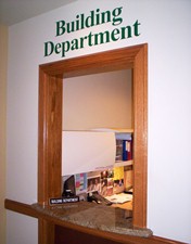
It is solely upon Purchaser to verify with Purchaser’s Planning and/or Building Departments, or any other appropriate government, or non-governmental agencies, the ability to construct purchased building(s) at location anticipated, as well as to apply for and obtain any needed permits. All due diligence to comply with any architectural or aesthetic covenants must be done by Purchaser, and Purchaser agrees to absorb any costs associated with compliance.
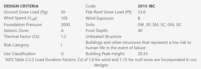
Purchaser acknowledges verification/confirmation/acceptance of all Building Code, Plan and Design Criteria included on Instant Invoice. Information Purchaser has verified includes, but is not limited to: Applicable Building Code version, Occupancy Category, Ground (Pg) and Flat Roof (Pf) Snow Loads, Roof Snow Exposure Factor (Ce), Thermal Factor (Ct), Wind Speed (vult or 3 second gust) and Wind Exposure, Allowable Foundation Pressure, Seismic Zone and Maximum Frost Depth, as well as obtaining for Seller any unusual code interpretations or amendments.
Seller’s designs are all per specified Building Code and include the use of NDS Table 2.3.2 Load Duration Factors (Cd) as well as ASCE 7, Eq. 7-2 for slippery surfaces. Seller’s designs rely solely upon occupancy category and structural criteria for and at specified job site address only, which have been provided and/or verified by Purchaser.
It is Purchaser’s and only Purchaser’s responsibility to ascertain the design loads utilized in this Agreement meet or exceed the actual dead loads imposed on the structure and the live loads imposed by the local building code or historical climactic records. Purchaser understands Seller and/or third party engineer(s) or agents will NOT be contacting anyone to confirm.
Dead loads specified on engineered roof truss drawings include the weight of the roof truss. Roof trusses are NOT designed to support ANY hanging loads or ceiling loads other than those specified as special truss loads in the Agreement. In the case of design roof truss bottom chord loads of less than five (5) psf (pounds per square foot) the bottom chord dead load may be sufficient only to cover the truss weight itself and may not allow for any additional load to be added to the bottom chord.
Roof truss top chord design loads of 5 psf (or less) are not adequate for roofing other than light gauge steel.
Seller recommends use of A1V (aluminum/single air cell/vinyl) radiant reflective barrier, an Integral Condensation Control (I.C.C. – Dripstop, Condenstop or similar), solid sheathing (with appropriate underlayment) or Purchaser applied 2″ or thicker closed cell spray foam insulation to help control roof condensation.
In no case is Seller liable for any condensation issues. An I.C.C., when ordered, is manufacturer applied to roof steel panels only. Seller makes no representation of any R or U value for any insulation or insulation products supplied. In the event Purchaser opts to utilize snow loads, wind loads, wind exposure factors, seismic loads or ventilation of less than those recommended by Seller, or soil bearing capacities greater than those recommended by Seller, Seller and third party engineer(s) are totally absolved of any and all structural responsibility.
Any windows and/or doors provided by Seller are NOT wind-rated, unless specifically noted as such.
Any possible design responsibility for this building is null and void should any structural materials and/or construction be substituted, replaced, depart, deviate, or are otherwise altered from the Seller’s original building kit they belong to, including structural materials from suppliers not authorized in writing by Seller’s owner, or if building is constructed at an address other than as specified on plans.
 Attached quote is how I would want my own building…..
 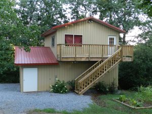 Wind Exposure B is a site protected from wind in all four directions, within 1500 feet, by trees, hills or other single-family home sized buildings. This would include building sites in residential neighborhoods and wooded areas. If your picturesque view is under ¼ mile, then this is probably you.
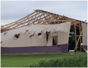 Surface roughness B = Exposure B with these restrictions:
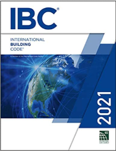 Exposure determination is not relegated to a nice, comfortable chart or table. This section’s main part explains ground roughness variations from natural topography and vegetation need to be take into account when determining Exposure Category.
 All proposals and agreements for buildings should mention what Code and Code version is being used. IRC (International Residential Code) and IBC (International Building Code) do have some differences between them. Every three years there is a new Code version published. Each version has latest updated changes due to testing, research and new products being introduced. Your new building should either match your jurisdiction’s adopted Code version or (if no structural permits are required), most recent version.
 #2 What Building Code will be applicable to this building?
 Every quote should include (at a minimum): engineer sealed plans specific to your building at your site. Complete Building Code information – including Code version (there is a new one every three years), Ground snow load (Pg), Flat roof snow load (Pf), Design wind speed (Vult or Vasd), Wind Exposure (there is a big difference between Exposure B and C) and assumed soil bearing pressures.
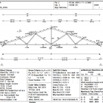 Planning on supporting a ceiling, either now or at a later date? If so a ceiling load of no less than five pounds per square foot (psf) should be indicated on engineered plans as well as a BCDL (Bottom Chord Dead Load) to match on sealed truss drawings.
 From cheapest up – a Radiant Reflective Barrier (aka bubble wrap – if going this route you only need single bubble, six foot wide rolls with an adhesive pull strip); Integral Condensation Control (
 If not, there is plenty left to chance. Hansen Pole Buildings provides a fully illustrated, step-by-step 500 page Construction Manual. And, if you get stuck, there is unlimited FREE Technical Support from people who have actually assembled buildings!
 There is no such thing as a “pole foundation engineering calculator” therefore, there is also no link to one. The design of post frame (pole) building foundations is one which is best left in the hands of RDPs (Registered Design Professionals – architects or engineers). When provided with all the pertinent information about your proposed building, they can design not only a structurally sound column embedment, but also your entire structure (which I whole heartedly recommend).

 For this particular client’s building site the Code wind speed design would be for 90 mph. There is a nifty little formula to convert mph to wind pressure (.00256 X wind speed squared). This makes a 150 mph wind speed applying 277% of the load force of 90 mph.
 Bob called to discuss the project, which was to have one long sidewall open, so recreational vehicles, tractors and other equipment could be parked. I asked Bob how wide the openings between the sidewall columns would need to be – to which he replied 12’. Quickly doing the math, I suggested he might want to consider 84’ in length, as 12’ evenly divides into 84’. Bob liked that idea.


