Tag Archives: j channel

Retro Installing Windows in a Spray Foamed Post Frame Building

Retro Installing Windows in a Spray Foamed Post Frame Wall

Reader JOEY in PRINCETON writes:

“Good Evening Pole Barn Guru! We need to add picture (9) and slider (3) windows to an existing 3-year old Sherman Pole Building Post frame building where we are converting part into living quarters. The building was spray foamed by the previous owner with closed cell foam, and upon some investigation (and confirmation by the builder – Sherman Pole Buildings) house wrap was not used. We need to order the windows for spring installation and are wondering how and what kind of windows to use. A salesman at Menards flippantly recommends using windows with a nail flange without brickmold. To assist our carpenter who will do the installation (with my assistance) I have searched high and low on the internet for a way to install the windows, but all I find are instructions on installation before steel is installed, and nothing with regards to existing spray foam insulation that is adhered to the steel. We realize we will need to scrape the foam insulation, so we are ready for the work involved. What advice can you offer? Do you have a window vendor to recommend? It would be greatly appreciated. I’ve attached pictures for your reference, Thanks for all your help.”


Mike the Pole Barn Guru says:
Joey is finding some challenges involved when it comes to doing a conversion from a barn to living quarters. Most post frame barns and accessory buildings are not engineered for residential structural requirements and unless one is 100% confident they have been appropriately engineered, a Registered Professional Engineer should be engaged to do a thorough site inspection and advise as to adequacy or structural repairs/upgrades.

I have given your situation a great deal of consideration, trying to weigh all involved factors of costs of materials, labor involved and end result. Here is what I would do:

In each bay (area between two columns) where an opening needs to be added, I would completely demo wall. Remove all insulation, girts and siding. I’d order replacement steel panels, install new girts, framing in new window openings, etc. New vinyl windows should be ordered with integral J Channels (sometimes referred to as J trim attached). These can be from any manufacturer and should be gas filled Low-E windows. Personally I feel it worth opting for triple pane windows in our climate. Going this demo and rebuild route will allow for sloped sill pans to be placed and self-adhesive flashing tape to be utilized.

In defense of your ‘Big Box’ salesperson – box stores and lumber dealers are unable to compensate help well enough to acquire, train and retain truly knowledgeable help.

Trying to scrape off your existing closed cell spray foam cleanly would be at very least a daunting task and is likely to damage some or all of your panels being scraped. Your only way to cut steel to properly fit windows snugly takes removal of steel panels, full length, as they need to be slid into place alongside windows.

Contractual Minimum Material Specifications

Disclaimer – this and subsequent articles on this subject are not intended to be legal advice, merely an example for discussions between you and your legal advisor.

Please keep in mind, many of these terms are applicable towards post frame building kits and would require edits for cases where a builder is providing erection services or materials and labor.

It never ceases to amaze me, when I read comments from people who have ordered a pole building kit, or a constructed building, and have little or no idea of how their building will go together, or what is or is not included. 

Wood Bending Strength
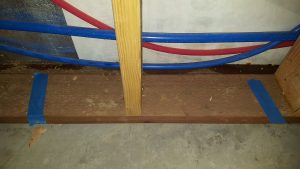
MINIMUM MATERIALS’ SPECIFICATIONS: (as applicable) Skirt Boards (splash planks): #2&btr pressure preservative treated to a minimum UC-4A specification. Structural Columns (those which support roof loads), pressure preservative treated to a minimum UC-4B specification. Spacing of wall columns is at Seller’s discretion unless specifically indicated on face of Agreement.

Wall Girts and Roof Purlins greater than 8′ in length, minimum #2&btr.

Prefabricated, engineered roof trusses, or rafters, at discretion of Seller, unless otherwise noted in the Agreement. On occasion, with sidewall overhangs, trusses may be shipped without tails – if so, appropriate lumber and hangers (as needed) will be furnished to field add overhangs. Lumber shall conform to the applicable grading agencies Standard Grading Rules. 

29 gauge steel roofing and siding. With steel roofing and siding and no sidewall overhangs, J Channel only shall be provided at tops of sidewalls as eave trim. No drip edge is included for steel roofing. Butyl tape sealant is supplied ONLY on roof steel overlaps for slopes of less than 3/12, unless by special order and indicated on face of invoice. 

Polycarbonate eave light panels are fastened with 1″ white screws nine inches on center. Ridge caps are fastened with roof steel colored stitch screws to each roofing high rib. 

Roof slope(s) not so specified in the Agreement are to be determined by Seller. Permanent roof truss chord bracing is as specified on third party E.O.R. sealed plans, which supersedes truss drawings. 

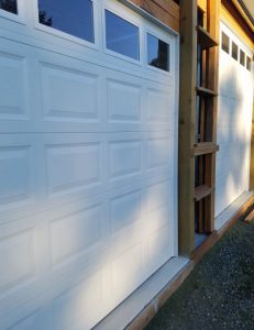
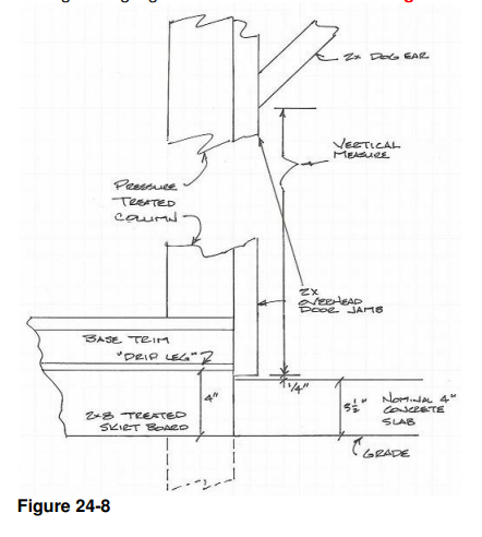
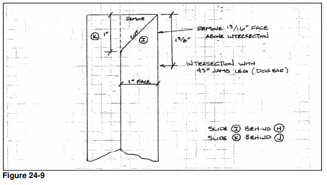
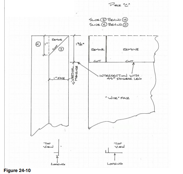
Sliding doors must be assembled on site, from provided components, will not seal airtight, do not include weather stripping and are not insulated. Sliding door jambs are ripped (by Purchaser) from Seller furnished 2×6 and are not pressure preservative treated as they are protected from weather when the door is closed.

Residential overhead doors may be approximately 2″ less in width and 1″ less in height than dimensions specified. Overhead door openings only are provided without vinyl weather seals. 

Pre-hung entry doors have 3-1/2″ jambs and may need to be installed swinging outward to facilitate full opening width. Doorknobs are usually positioned to be equidistant from top and bottom of doors. Seller is entitled to make substitutions of materials or equipment which Seller deems to be equivalent in performance to materials specified in the Agreement. 

At Seller’s option, roof radiant reflective barrier may be replaced by felt (or other similar barrier) over oriented strand board, without the need for a Change Order. When needed for shear wall requirements, Purchaser will not unduly prevent Seller from relocating any doors, windows, or other openings. 

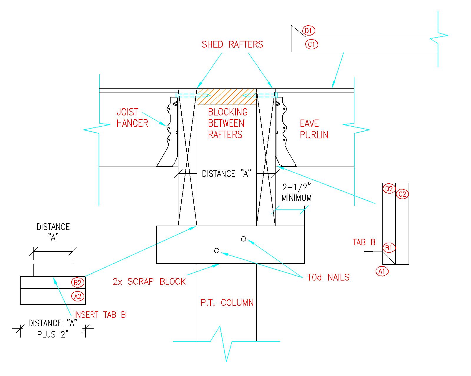
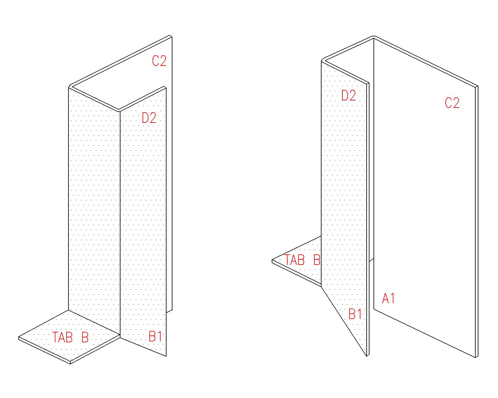
Any shearwall or diaphragm blocking shall be as specified on third party E.O.R. sealed plans. Seller’s plans and instructions may deviate from component manufacturer’s installation instructions and manuals, due to judicious experience, and Purchaser acknowledges any such deviations are not cause for rejection or demands for extra or alternate materials.

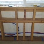
Interior wall framing included only as specified on face of Agreement.

Eave height is the measure from the bottom of the pressure preservative treated skirt board (splash plank) (grade), to the underside of the roof steel (or other roofing material) at the outside of the sidewall double truss bearing columns. 

Interior clear height, allowing for a nominal four inch concrete floor, will be ten inches or more less than the eave height. It is the responsibility of Purchaser to determine if eave height, width and height of door openings, or provided doors, is adequate for Purchaser’s needs.

MINIMUM QUALITY SPECIFICATIONS: Steel roofing and siding may naturally dimple at through fasteners or ripple between supports, and as such, neither is a defect. Steel trims may be subject to oil canning, or other expansion and contraction conditions after installation – this is not a product defect. Although every good faith effort will be made, no guarantee is possible to exactly match any colors, to existing materials. Commercial overhead doors may be primed only, and as such, color variations and/or scratches are not defects.

PURCHASER SUPPLIED MATERIALS: Purchaser clearly understands Purchaser will under no circumstances be reimbursed for the purchase of any replacement materials for any reason (including suspected damage or shortage) without the prior written authorization of Seller, or Seller’s suppliers.

This one pertains specifically when a building is being erected by a contractor:

PURCHASER SUPPLIED LABOR: Any work performed by purchaser is strictly prohibited without Seller’s written consent, however Purchaser may supply his own labor, without adjustment of the agreement price, with the exception of the column holes “where applicable”. Should the Purchaser opt to excavate their own column holes, Seller will furnish Purchaser with a layout only, and Purchaser must properly locate the same. 

Column holes properly located, excavated and cleaned out by Purchaser, passing Building Department inspection will be credited at $10 per hole. For structures where columns are supported by brackets, purchaser to supply all equipment, and labor to properly embed into new concrete, except as otherwise noted. Purchaser is responsible for the timeliness and quality of all labor furnished by Purchaser, and is responsible for the performance of such work according to Seller’s schedule. Purchaser is responsible for Seller’s extra costs pursuant to section xx of this agreement, “change orders”, for extra costs incurred as a consequence of Purchaser’s failure to perform own labor in a timely manner without defect.

R Panel Gable Vents

R Panel Gable Vents

“R” steel roofing and siding panels are typically used on all steel buildings where larger spans occur between wall girts and roof purlins. With a three foot width net coverage, these panels have a 1-1/4 inch tall high rib every 12 inches with two low stiffener ribs between. R panels do not have a full underlapping (or purlin bearing) underlap. This lack of a purlin bearing underlap makes this product both less expensive (as it can be roll formed out of a narrower steel coil) and more difficult to install. Without careful placement at laps, panels tend to “walk” with one or both panel ends covering more or less than the necessary three feet.

Very few all steel buildings make provisions for ventilation. Rarely do they include sidewall eave overhangs, leaving no place for an eave air intake through a vented soffit.

So, how to vent?

Reader STEVE in PHOENIX writes: “Mike,
Hello. I’ve been researching venting options for an existing clearspan type red steel metal building and was directed to your snap in style gable vents for ribbed metal panels.  My building is covered with R panel metal siding…..the high ribs are 12″ on center (pic attached). I’ve been working with Justine on selection and pricing of your gable vents.  Will your vent panels work with this siding and if not, do you have a venting solution for this building? Thanks.”

My reply:

R panels typically have 1-1/4″ high ribs. I do not believe the snap ring vents will work with ribs higher than 3/4″ (Justine can confirm). If not, then you could use a standard gable vent with a J Channel surround. Just like snap ring applications, cut the hole in siding for the vent (make it 1/4″ taller and wider than the vent you will push through the hole). Cut J Channels to fit the vent, with interlocking and overlapping corners (just like a non-integrated J Channel window). Insert individual pieces of J Channel into the hole, joining corners as you go. Slide vent into J Channel “picture frame” using lots of caulking between vent and J Channel and at each of the J Channel corners.


Snap ring vinyl gable vents (https://www.hansenpolebuildings.com/2018/07/vinyl-gable-vents-for-pole-barns/) make installation a breeze and can quickly be installed in post frame buildings with steel siding with ribs no higher than ¾” . When designing your new post frame building discuss ventilation with your Hansen Pole Buildings’ Designer at (866)200-9657.

Placing Steel Trim Around Post Frame Shed Rafters

Reader HEATH in NACOGDOCHES writes:

“I am going to build a pole barn with shed roofs. I want to know what the best way to trim out under the sheds where the side wall meets the ledger board or bottom of rafters. Building will be sheeted with metal. There will not be any soffit under sheds. Rafters will be exposed. Do you have any pics that I could see of this detail?”

Mike the Pole Barn Guru responds:

This is just one of a plethora of subjects covered in Hansen Pole Buildings’ Construction Manual:

Trim Around Rafters Through Sided Eave Wall

Install a 2x block (cut from scrap) to extend a minimum of 2-1/2” past most extreme edges of rafter combination to outside column face directly below rafters.  See Figure 42-8

 To avoid running out of J Channel, install all longer lengths first, and then use cutoffs for these shorter segments.

Cut to length a J Channel piece to fit between rafter assemblies. 1” face (3/4” for ABC trims, 7/8” for McElroy) will be cut back from “J” bottom at a 45-degree angle. Tack in place this J Channel piece to eave strut snug to roof steel. See Figure 42-6

Figure 42-6  J Channel Cutting for Rafter Tails

Square cut a J Channel piece to Distance “A” plus 2” long (for trims provided by ABC use 1-1/2” to Distance “A”; McElroy 1-3/4”).  

Using snips, cut 1” (for ABC trim 3/4”, McElroy 7/8”) in from each end along J Channel bends.  Holding J Channel like an inverted “J”, bend up two tabs created between cuts. See Figure 42-7

Figure 42-7  Cutting tabs on J Channel

Install this trim piece tight underneath overhanging truss tails, with folded-up tabs on each side.  See Figure 42-8

Figure 42-8 Cutting Trim Pieces for Through Rafters

Next install vertical J Channel pieces along front and rear faces of rafters. These piece lengths will vary depending upon roof slope and rafter size.

Top end (fitting tight against roof steel) will be square cut.  Lower end will again have bends each cut, with snips, up 1”.

Fold area between cuts to form a tab. 1” J Channel face (3/4” face for ABC trims, 7/8” for McElroy) is to be cut at a 45-degree angle.  

Install vertical pieces so area labeled A1 is on top of A2.  Tab B will be inserted into inverted J top below truss tails.  See Figure 42-9

Figure 42-9  Inserting Trim Pieces Below Rafter Tails

Face B1 will be on top of Face B2; C2 will be behind C1 and D2 behind D1.

Carefully determine where rafters will lie along sidewall steel. This can be done by installing full-length panels along wall until a rafter is reached.

Easiest, if grade allows, slide panel to be cut up against trimmed out rafter assembly underside and put light pencil marks on steel to align with front and rear faces of rafter assembly.

J

When done properly, no light will shine into building from this area.  If light does show through, use an appropriate mastic or caulk to seal area thoroughly.

The Case of the Leaking Post Frame Building Window

The Case of The Leaking Post Frame Building Window

Sir Arthur Conan Doyle’s hero – renowned sleuth Sherlock Holmes, was forever solving mysteries entitled “The Case of Something or Other”. To solve this particular mystery neither Holmes, nor Dr. John Watson’s skills will be required. Nor shall we need a call to Scotland Yard.

Reader Justin in California writes:

“Hi

I’m hoping you can tell me the truth about why windows might be leaking in a pole barn with metal siding.

I’m in California and had a local builder put this building up.

All of my windows leak…well they seep.


It’s not a lot and only happens when it rains a lot or rains with winds.


I see there is a water trail starting at the bottom of all windows and goes down.


I have attached photos of the inside and outside.


I was told that water hits the J channel then goes down and goes between the metal siding and the window wrap (Tyvec) and out the bottom….is this true?


Not asking for a fix just does that water travel between metal and the wrap?

Thanks.

P.S.

The blue frog tape marks where the leaks are.

The photos w/ the pex pipe…the water has been turned off so no water leaks coming from the pex pipe.”

Mike the Pole Barn Guru writes:

There’s truth as to why you are getting leakage around your windows (drum roll please) – poor installation.

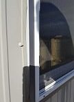
Another truth – water hits your building’s J channel then goes down and goes between the metal siding and window wrap (Tyvec) and out the bottom. This does not make it a correct installation however.

When I was constructing post frame buildings two decades ago we initially were doing an installation similar to what your builder did. We used a typical flanged vinyl window and trimmed it out with a surround of four sticks of J Channel. I had some really great building crews, guys who took a great deal of pride in their workmanship. Even then, we had call backs for over 10% of our window installations due to leaks! Construction callbacks are costly and crews hate going back to do rework. We solved this problem by going to vinyl windows with integrated J Channels. Poof – leak problems pretty much disappeared.

Your building has a Weather Resistant Barrier (good choice as it allows moisture from inside wall cavity to pass out, while keeping outside moisture out).

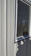
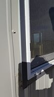
Before placing a window in a framed opening, a generous bead of caulking should be applied to seal between nailing flange and Weather Resistant Barrier. After installing window in opening, place self-adhesive flashing tape (3M All Weather Flashing Tape 8067 or similar) around the window. With steel trim J Channel, a serious bead of caulking must be placed between flashing tape (or flange if tape was omitted). As J Channel corners are overlapped, caulking needs to be placed between each overlap. Special attention needs to be given to lower corners of window to adequately and completely seal tops of ribs, so water running down panels cannot get between steel siding and Weather Resistant Barrier.

Inside closures (https://www.hansenpolebuildings.com/2015/12/the-lowly-inside-closure/) or Emseal Self Expanding Sealant Tape Closures (https://www.hansenpolebuildings.com/2016/03/emseal-self-expanding-sealant-tape-closures/) can be placed between top edge of steel siding below window and Weather Resistant Barrier to further limit a possibility of water entering your walls.

Wa-lah! Case solved.


Help! My Overhead Door Jambs are Rotting!

Help! My Overhead Door Jambs Are Rotting!

I am fairly certain this problem occurs more often than I hear about. Reader DAVID in ROLLING PRAIRIE writes:

“Enclosed are two pictures showing my pole building’s overhead door. One picture is the inside door jamb that is decaying from water damage and the other one is a picture of the outside J channel and siding above the overhead door. My question what items need to be removed and what needs to be done to repair and seal the inside door jamb area? This an FBi building built in 1989. The outside upper J channel appears not to be sagging and there is no evidence of any leaks from roofing or front walls.


Thank you in advance for any help given.”

Mike the Pole Building Guru responds:

Thank you for sending photos. As you can tell from photo of outside J Channel, water has been collecting in channel, resulting in wall steel deterioration. Water most likely enters your building through one or more of – a hole or holes have rusted through J Channel, an uncaulked splice along top jamb length, or poorly executed (and possibly uncaulked) trim intersection at opening corners.

If it was my own building, I would approach a solution in this fashion:

In order to repair this area properly will involve having to remove some siding. Your building’s siding was fastened with nails, meaning it will be destroyed in removal process. Therefore, I’d remove all steel siding and trims from this building wall and replace them. Over 29 years your paint has faded and chalked significantly. For replacement I would go with Kynar painted panels (read more about Kynar here: https://www.hansenpolebuildings.com/?s=Kynar). While in steel replacement mode, I would add wainscot to this wall, regardless of whether building balance has it or not. Wainscot will enhance your building’s appearance, as well as providing short length panels easily replaced if damaged.

I would remove present overhead door jamb boards and, as a precautionary measure, replace them with pressure preservative treated lumber. Any cut ends I would treat liberally with Copper Napthenate solution. Cover the entire framed wall with Weather Resistant Barrier (think Tyvek). Wrap barrier completely around wood jambs and staple to inside wall. Wooden overhead jambs should be covered with steel trim with an integrated J Channel to receive siding. Place self-adhesive flashing tape (3M All Weather Flashing Tape 8067 or similar) between weather resistant barrier and overhead jamb trim. Avoid a splice in horizontal trim across the top, if possible. Some steel roll formers will make trims long enough for a 16 foot wide door. Overlap trims at corners so any water potentially seeping in rolls onto yet another steel piece. Place liberal caulking amounts behind and between any trim splices or overlaps, especially near corners.

When installing steel siding above door opening, cut panels so bottom edge lands 1/2″ above integrated J Channel low point. This will reduce steel panel premature decay possibility. Use form fitted inside closure strips between these panels and jamb trim flange above the door opening.

Good luck, and please do send me pictures of the final result!


Garage Door Trims Don’t Fit

Garage Door Trims Don’t Fit

Hansen Pole Buildings’ Technical Support Department answers lots of questions for our clients. Most of these questions can be answered, or could be solved, by review of the building’s engineered plans and/or reading appropriate chapter of Hansen Pole Buildings’ Construction Manual. This Construction Manual also provides a step-by-step outline of in what order to assemble a post frame building kit, so as to achieve best results.

Short Panel Door
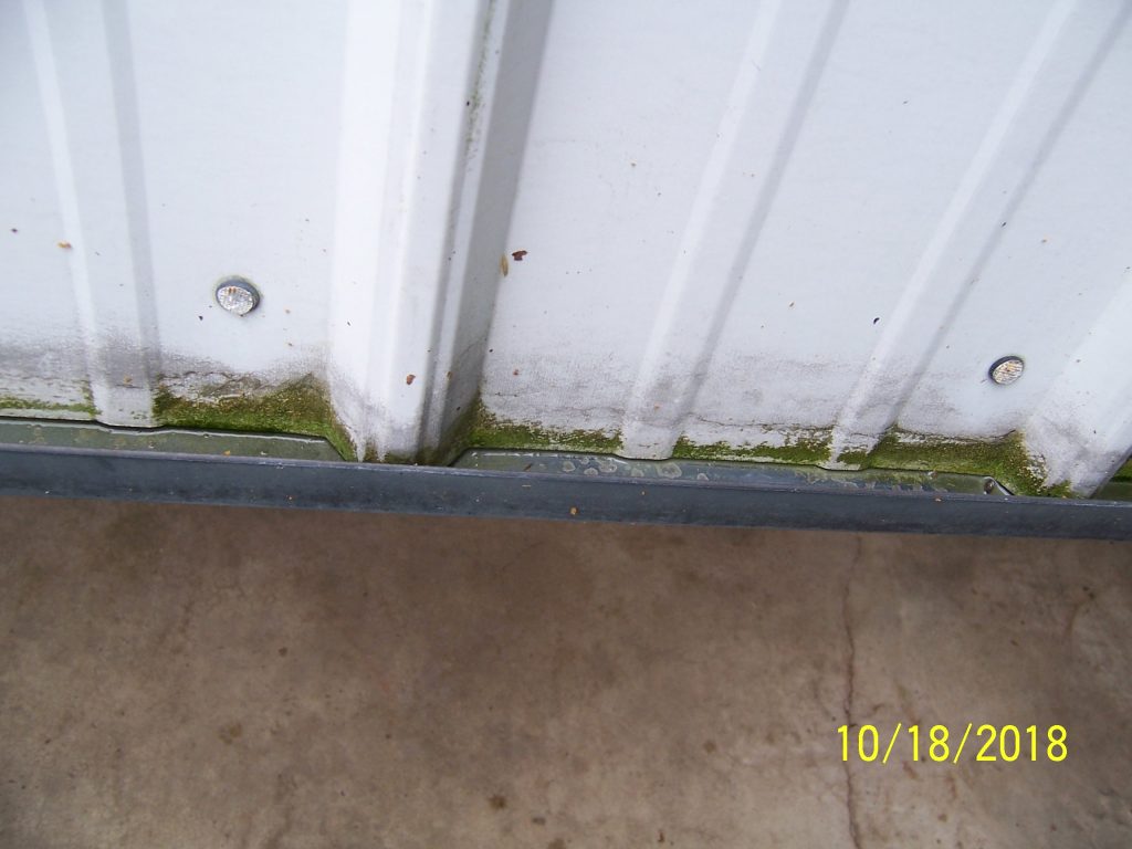
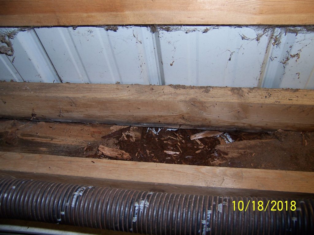
Sadly, some folks go astray (more often than not – builders whom have their own ideas) and end up with some unique challenges. Challenges we are here to help solve, even for clients who began construction two (or more) years ago.

Client SCOTT in RUFUS writes:

“I have been a long time at putting up this building due to working full time etc. I am at the point of putting on garage door trims. If I understand the orientation of these trims, I have 7 1/2″ of trim and 7″ of space to cover. It looks like I will have to cut 1/2″ down the entire length of each of these trims. Can you give me any advice or thoughts on this? See the attached pictures. Thank you, Scott”

We experienced some considerable head scratching initially, before we opened up client’s photo seen with this article, then it became clear what challenges truly existed.

Hansen Pole Buildings’ overhead door jamb trims started with a standard part manufactured by McElroy Metals known as a P-JFB We have since introduced this part to our other steel vendors, a jamb trim with an integrated J channel. J channel receives edge of steel siding and jamb trim portion sized to cover an appropriate sized jamb, in this client’s case a 2×8.

Sometimes the solution is as easy as using the right trim in the right place.

Overhead Door Jamb


P-JFB trim for a 2×6 jamb shown above.

Here was fix for this client:

We can’t say we have seen overhead doors installed before door jambs are in place (or for this matter headers not yet in placed outside of columns). In order to solve your challenge you are going to need to carefully remove vinyl weather seals from around installed doors. Next loosen all lags attaching vertical legs of overhead door tracks to allow for about 1/2″ of “slop”.

Carefully read Chapter 24 of Hansen Pole Buildings’ Construction Manual “Residential Overhead Door Openings”.

Install overhead door headers appropriately to face of building columns. Place 2×8 overhead door jambs in overhead door hole, with outside of 2×8 even with outside face of headers, wall girts and skirt boards. Install jamb trims, with excess beyond dimension of 2×8 jambs (if any) towards door. Tighten lags holding vertical door rails down, so overhead door face contacts with jamb trims. It may be necessary to replace lags with longer ones, in order to achieve a solid bite into columns. You will probably need some shims between overhead door side rail brackets and columns, in order to tighten lags without a space between brackets and column. Reinstall vinyl weather seals.


No Leak Overhead Door Dog Ears

No Leak Overhead Door Dog Ears
The key to cutting trims for no leak overhead door dog ears for post frame buildings comes from careful cutting and installation of pieces to water flows in front of, rather than getting behind, each piece as it works down the building. It also helps to utilize a trim which covers the jambs and has an integrated J Channel.

Today’s article was prompted by a question posed by reader JOE in TERREBONNE:
“Could you please tell me the process for wrapping the metal trim around overhead doors with diagonal corners so they don’t leak. I’ve heard that using the angled corners will always leak. Any help will be greatly appreciated.”

Mike the Pole Barn Guru Responds:
The following is excerpted from the Hansen Pole Buildings Construction Manual.
All drawings for this depict door opening LEFT side. Mirror image for right side. Drawings are based upon McElroy Metals’ parts (The same process can be used for any manufacturer’s part, provided appropriate adjustments are made for dimensional differences)..

Step #1:

Square cut two P-JFB trim pieces to the measure from 1/4″ above top of concrete slab to 45 degree dog leg bottom and ADD 1-3/8″. See Figure 24-8

Figure 24-8: Overhead Door Flashing Front View

Cut top end as indicated in Figure 24-9 and Figure 24-10 . This becomes Piece C.

Figure 24-9: Overhead Door Flashing Cutting Diagram

Figure 24-10: Nailing Overhead Door Flashing Into Jamb

Install piece C, using joist hanger nails through approximately 2” back face of the “J” portion into the 1-1/2” edge of the jamb. Nails should be close to each end and approximately every 2’ to 3’.

On the wide inside face of the overhead door jamb the trim will fasten when you are ready to install your overhead door weatherseal to the inside face. Nail your weatherseal on with nails every 3′ on center along the entire jamb.

Step #2:

Square cut two P-JFB pieces to 19-3/4″.

Cut one end as shown in
Figure 24-11.

Figure 24-11: P-JFB Piece B Low End

Cut opposite end as shown in Figure 24-12.

Figure 24-12: P-JFB Piece B Installation
Piece B

Install Piece B

Step #3:

(Depending upon door width, this step may require 2 P-JFB pieces.)

Cut each end as shown in Figure 24-13.

Figure 24-13: P-JFB on Dog Eared Door Openings

F Channel and Enclosed Soffits

My early days of post frame (pole) buildings came in the Pacific Northwest. In the early years, rarely did buildings have any overhangs…at least not beyond a few inches of roof steel extending past the siding.
When building did have overhangs, they were always “open”. Open, in this sense, did not mean birds and other critters could fly into the building through them, but rather they had no soffits.

With an open overhang, when one stands beneath and looks up at the underside of the overhang, the supporting substructure framing is visible, as is the underside of the roof steel, or roof sheathing.

A decade later and a transition from a provider of post frame building kit packages, to being a pole builder and clients began requesting their buildings to have enclosed overhangs. With a minimal investment over open overhangs, plus the advantages of being very attractive and limiting locations for nests of both barn swallows and wasps – it was (in my mind) a no brainer.

In researching how others were installing soffits, I found the majority use a piece of trim called an F and J up against the building sidewall.

f channel
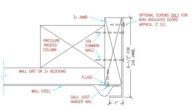
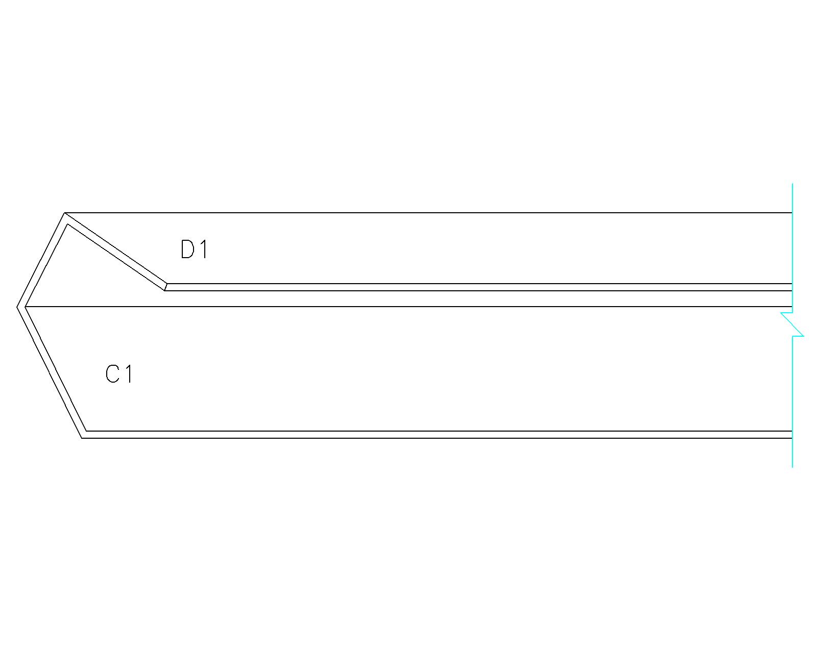
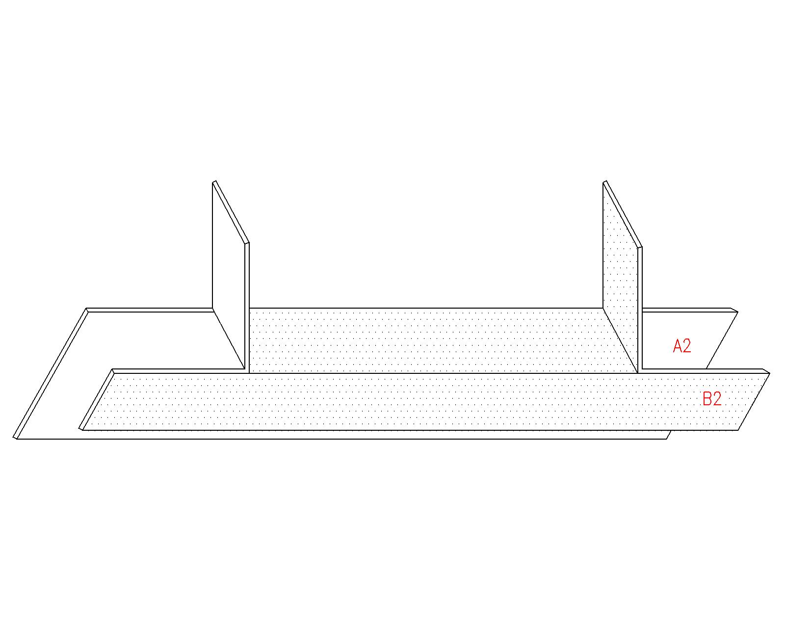
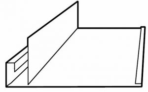
Picture an F channel with the downward leg being attached to a horizontal piece of wall framing, usually by nails. The horizontal “legs” of the F receive the soffit material – usually vinyl, steel or aluminum. From the end of the short (and lower) horizontal leg of the F channel, is another downward leg (envision an inverted J). The sidewall steel then slides up into the J from below.

All of this appears to be a quick and easy install. Nail a single 2×4 against the outside of the columns, attach the F and J to it and slide the soffit panels into the F channel.

Now the problem with this (as happens with quick and easy) – the soffit panels are not attached to the F. When the breeze begins to blow, the soffit panels vibrate in the F channel, making noise. As wind speeds increase, the soffit panels can actually be blown out of the F – creating all sorts of challenges.

So how did we solve the challenge?

Instead of a single 2×4 nailed to the face of the columns, we took two 2x4s and nailed them together to form an inverted L. The short leg of the L now gives something solid to attach the soffit panels to. Below the soffit panels an inverted piece of J channel trim is installed, easily attached to the vertical leg of the 2×4 L.

I’ve now experienced several thousand soffit installations using this procedure and have yet to have a report of a single soffit panel being blown out!

Success.