Understanding How to Size Rafters
Reader ANDY in SHELBYVILLE writes:
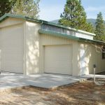 “I’m looking for an explanation on how to size a rafter on the side of an existing pole barn. The lean-to will be 12′ wide, 80′ long, ~10 height on the inside, pole barn post are 8′ spacing. I was planning on using 2×4 on end for the purling on top of the rafters. I am looking to understand how to size the rafters not just an answer like use 2×8 or 2×10. I’m finding it hard to find any explanations on how the purling affect the rafters sizing. I see lots of rafters spacing at 18″ and 24″ but nothing when using 8′ spacing. Thanks for any assistance.”
As you are in Shelbyville (where my oldest daughter Bailey lives and trains Tennessee Walking Horses), here is how to calculate rafters yourself.
Purlin dimensions and orientation have no affect upon rafter sizing.
First, check for adequacy in bending:
[(Plive + Pdead)] x rafter spacing in inches x rafter span (in feet) squared / (8 x Sm x Fb x Cd x Cr) must be less than or equal to one (1)Plive = live load where Code minimum is 20 psf
Pdead = roof dead load, for steel roofing, purlins, weight of rafter and a condensation barrier could be as little as 3.3 psf (we typically use 5 psf)
Sm = section modulus of board chosen and is calculated by taking board width (1.5″) x board depth (5.5″ for 2×6 or 7.25″ for 2×8) squared and divide by 8. 2×6 = 7.5625 2×8 = 13.1406 2×10 = 21.3906 2×12 = 31.6406
Fb = Fiberstress in bending (Can be looked up here: https://awc.org/wp-content/uploads/2021/10/AWC_NDS2018-Supplement_20200827_AWCWebsite_Chapter4.pdf) NOTE: Lumber values are specific to lumber species and grade, this is why they must be looked up.
Cd = Is Duration of Load, if little or no snow = 1.25, if Pg (ground snow load) is 20 or more = 1.15, in areas where snow remains on roofs for extended periods = 1.0
Cr = 1.15 if rafters are 24″ or less on center, else = 1
Second, check for deflection:
Δmax = (5 × w × l4) / (384 × E′ × I)
Where
w = pounds per linear inch of beam from snow (or live load) only 20 psf /12″ (converting feet to inches) x spacing of rafters (in inches)/12″
l – span of rafter in inches
E = modulus of elasticity (Again. can be looked up here: https://awc.org/wp-content/uploads/2021/10/AWC_NDS2018-Supplement_20200827_AWCWebsite_Chapter4.pdf)
I = width of member divided by depth of member^3 / 12 for 2×6 = 20.79; 2×8 = 47.63; 2×10 = 98.93; 2×12 = 177.97
Δallow = l / 150 IBC Table 1604.3 Footnote a
![]()
Δmax = (5 × w × l4) / (384 × E′ × I)
Δmax must be less than or equal to Δallow
And now you know why we hire engineers to perform structural calculations.
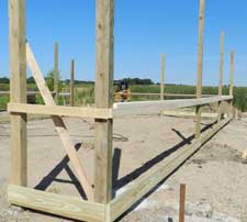
I would look to place a rafter on each side of columns, then joist hang purlins between rafters. Purlins on edge, going over top of rafters, being a questionable attachment and purlins should then have solid blocking between them at rafter to prevent rotation.

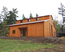
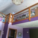 1. It Looks Amazing
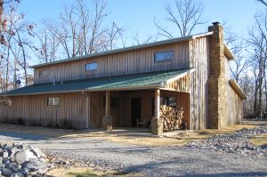
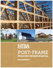 The NFBA has risen to the occasion with the recent introduction of the new Post-Frame Building Design Manual! The second edition of the manual—and the first new edition since 2000—is the ultimate tool for post-frame design. Eight chapters, 200 pages, and hundreds of photos, diagrams, illustrations and design tables cover everything you need to know about designing with post frame.
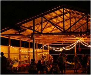 Back in 2005, my friends Sheri and Larry Herberholz had an idea – it involved a pole building, alcohol and lots of motorcycles and Hot Rods. This great concept became
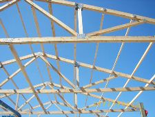
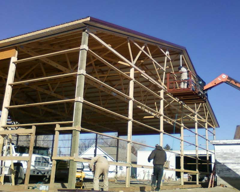
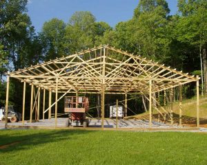 How thoroughly are members (framing pieces) checked? Every direction possible for climactic forces (such as wind, rain and snow) and seismic forces, as well as construction loads and the weight of the building itself. Our engineering program runs all the mathematical calculations as if these forces are applied to every piece of the building. It then chooses the appropriate lumber and parts to put them together (ledgerloks, bolts, LSTA straps, nails etc.) to ensure every building is designed to not only meet, but exceed stated code requirements.
 From then on, I started using double trusses, nailed together according to a specific nailing pattern (supplied on all our plans). Since then we’ve had other winters with similar ice/snow loadings, and…no more failed roofs! I had the engineer’s word, but even better – I had real proof from thousands of buildings which survived nature’s “test”. We’ve been using the double interior trusses ever since. Only one roof I’ve seen fail since then…and it was determined to have been due to the two trusses were not nailed together adequately – they had few nails holding them together. Again – the trusses acted as “singles” and pulled part of a roof down.


