Heave Ho
Reader TIM in HUNTER writes:
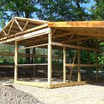
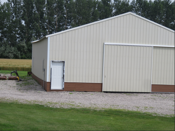
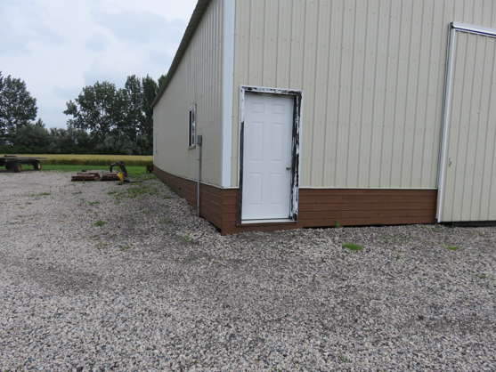
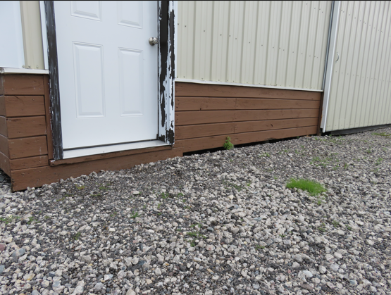
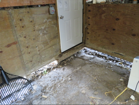
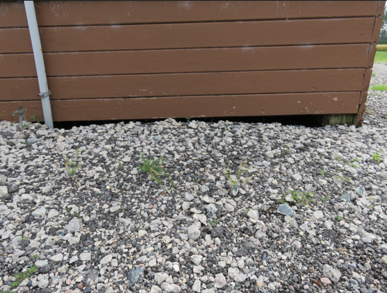
“I have a pole building, dirt floor no concrete that has heaved up in one corner about 12 inches. I think the builder put Quick Crete in the hole of each posts. I realize it is caused by frost. The frost free hydrant located near the corner has leaked where the connection is attached to the pipe underground and this will be the third time in 20 years that I have to dig it up and have it repaired. I noticed the starting heaving about 4 or 5 years ago. My question is how to fix the issue. As no one around here in the construction business has any idea, other than a dirt contractor that thinks we can dig a channel and let the weight of the building push it back down. This comes with the challenge of deflection that could destroy all or part of the building it has heaved up about 12 inches, but there are no cracks in the rafters, stringers, or posts. See attached pictures. I really need some help in determining what to do! Pictures attached. Thank-You!”
Your dirt contractor is actually on a correct right path. This is not going to be easy, but it should preserve your building and keep issue from repeating.
At each “lifted” column, doing so one column at a time, dig down around column far enough to place a 2x6x12′ on edge (running perpendicular to wall) each side of column (centered on column) and secure with structural screws. Repeat until all lifted columns have been braced. Now, dig channel along wall at least four feet wide (need to have at least two feet on each side of exterior side of wall), extending to below current quick crete footings, and deep enough to allow building to fully be able to ‘settle’. One raised column at a time, dig an inch of soil out from under 2×6 braces. Repeat this cycle until each column has settled into an eave level position.
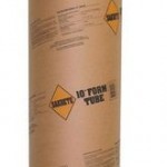
Next, pour new concrete footings around each previously offending column. You can use a 2′ diameter sonotube as a form (make a vertical cut in tube to allow to slip around columns), with top of tube being 22″ below bottom of splash plank.
Remove 2×6 braces.
Beyond channel, install a french drain.
Fill channel up to top of tubes with crushed gravel, compacting every six inches.
Place a 48″ wide piece of R-10 EPS or XPS rigid insulation board horizontally on top of gravel, with outside edge 2′ beyond columns.
Place another 24″ wide piece of insulation board on top of center of horizontal board and attach top to inside of splash plank. You are forming an inverted “T” with insulation boards. These insulation boards will help to keep frost from forming in ground at columns and having a repeat performance.
Carefully backfill with more crushed gravel, up to grade.
Finish grade sloping down from building six inches in 10 feet.
Install gutters, with ends of downspouts at least 10 feet from building.
 DEAR DIGGING: If you think about it, a sonotube filled with concrete and a bracket on top, is going to provide less lateral resistance than a column in a hole filled with concrete. Depending upon building dimensions, exposure to wind and soil conditions above the bedrock, it is very possible increasing hole diameter and using a complete concrete encasement could do the trick.
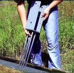 Provided column holes were not backfilled with pre-mix concrete (they probably were not), you could temporarily support any given deteriorated column above grade, then cut off the column just above top of concrete slab. From outside, excavate around offending column and remove it. Coat cutoff column bottom end with a waterproof sealant, such as an asphalt emulsion. Place a Sturdi-Wall Plus® wet set bracket on bottom of cutoff upper portion of the column. Clean all loose dirt from bottom of excavation. Use an appropriately sized Sonotube® extending down to at least below frost-line and backfill tube with premix concrete. Backfill around exterior of tube with compactable fill, compacting to at least 95%, no less often than every six inches.
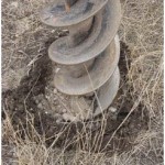 I used to take a steel stake used for anchoring concrete forms and a sledge hammer to investigate job sites prior to digging. Once building hole locations were laid out, said stake could be driven in at each hole location to determine if there were challenges ahead which could not be seen on the surface. At least by doing this stake test, we could determine with some degree of accuracy where challenges might lay, and if we thought we were going to have one, negotiate with our new building owner about shifting building location to avoid isolated rock.
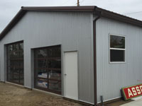 Things to consider with this method of mounting columns, rather than embedding them – cost of sonotubes (an 18″ diameter tube 4′ long will run around $20), a little over twice as much concrete will be needed for holes (roughly $15 on an 18″ diameter hole), brackets (roughly $50 plus shipping) and mounting hardware. This will be offset slightly by columns being four feet shorter in length. Due to soil bearing capacities, there are many instances where larger diameter holes will be needed, but for this discussion’s sake – probably $75 per hole in minimum added investment is not unrealistic.
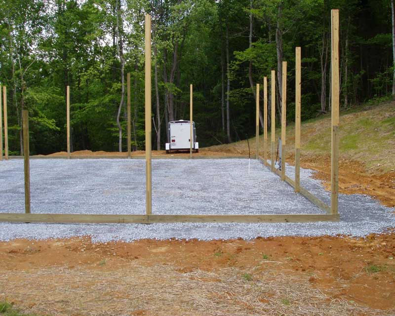 At a minimum, site preparation includes: