Tag Archives: dimensional lumber

Flat Use Factor (Cfu) for Dimensional Lumber

Flat Use Factor (Cfu) for Dimensional Lumber

For those who have not had their eyes glaze over from my recent articles on S (or Sm) Section Modulus or Cf (size factor adjustments), I bring, in all its glory, Cfu (Flat Use Factor).

Although produced in a factory environment (a saw mill), wood is a non-uniform material and doesn’t behave identically when bent about different axes (yes, this is plural of axis). Tabulated strength values are always based upon strong axis (x-x direction), so a modifier was created based upon actual physical testing, to adjust for loads placed about a board’s weak axis (against wide face, or y-y).

Look at it this way, if a board has a knot in one spot, and is bent about its strong axis, said knot may have a significant effect on overall strength, since this knot can alter effective depth (d).

Lay board flat and a knot only effects a portion of width (b), so effect on flexural (bending) strength is less pronounced.

Allowable bending strength (Fb) is based upon strong axis bending and takes into account statistical variation of flaws and their effect on “d” (depth). When used flatwise, Fb values can be increased to account for this less pronounced effect.

Looking at this example, if this was a joist (or purlin) bent about its strong axis, this knot will significantly affect allowable tension or compression stress, in joist’s extreme fiber. However, used flatwise, affected area is only a portion of extreme fiber and thus defect is less important. Wood allowable stress values are based on some amount of defects and thus they are already reduced for strong axis bending. In weak axis bending this assumption is taken out.

For 2×4 and 2×5 Cfu = 1.1, 2×6 and 2×8 = 1.15, 2×10 and wider = 1.2.


Designing a Dream Barndominium Loft

Designing a Dream Barndominium Loft

Reader BRIAN in PETOSKY writes:

“ Hi Mike,

Mindi told me to email you my lofted floor question for our project.

To avoid messing with truss-support floors, we were planning to build a full 26×60 main barn with scissor trusses the full length. Then on one end, we would make a 20’x26′ loft. Have the floor joists run parallel to the barn, perpendicular to the trusses, so we’d have 20′ floor joists. These would be supported by the gable end wall and interior posts 20′ in.

We live in a barn home with this configuration and it works well. Allows consistent and uninterrupted ceiling space the length of the barn but still get a 2nd floor in where we want it.

The question is, I guess, what, if anything needs to be conveyed to the engineer for this design? Does it influence anything on the gable end wall? How far apart can the posts be on the interior end? Can stairs be free-standing next to this loft?

Thank you!”

When I used to call on Home Depots, Petoskey was one of my stops. Every time I was there the weather was gorgeous, making it difficult to get motivated to move on to my next appointment!

There are some challenges with running dimensional lumber floor joists to span 20′. Even using #2 & better 2×12 Douglas Fir joists, they would need to be 12 inches on center! Other popular specie of framing lumber has lower MOE (Modulus of Elasticity) values, so will not even begin to approach being able to span 20’. Chances are good there will be both a fair amount of spring to this floor, as well as a non-uniformity in deflection from joist to joist.

For extended reading on floor deflection, please read https://www.hansenpolebuildings.com/2015/12/wood-floors-deflection-and-vibration/

This would be my recommendation – we can use prefabricated wood floor trusses to span 26′. Doing so would allow there to be no interior supports within this 26′ x 20′ area. As long as stairs run perpendicular to the floor trusses, no columns would be needed where they attach. When you and Mindi have your building details finalized, she will relay this information forward on your Agreement with us, so everyone will be on the same page. Further, we send plans to you for a final once over prior to engineer sealing them, just in case.

Stick Frame and Some Limitations

Stick Frame and Some Limitations


Perhaps stick built construction’s biggest advantage is builders and tradespeople are very comfortable working in and around stick framing. All registered architects and most building inspectors are very familiar with stick framing. The International Residential Code (IRC) provides a prescriptive ‘cook book’ to follow for adequate structural assembly, within certain limitations. These limitations include, but are not limited to, no story height of greater than 11 feet 7 inches (R301.3), no hurricane prone areas with a design wind speed of 130 mph or greater located south of Virginia, or 140 mph elsewhere (R301.2(5)B), and no ground snow loads over 70 psf (R301.2.3).

IRC802.10.2.1 further limits truss spans to a maximum of 36 feet and building lengths to 60 feet (measured perpendicular to truss span). Trussed roof slopes must be at least 3:12 and no greater than 12:12.

Wood is a very forgiving building material and, even when miscut, replacement material is usually only a short drive away. America’s home building industry has built traditional, wood stick framed homes, on site for decades.

Many builders, architects, carpenters and other subcontractors prefer to work on stick built homes as compared to alternative building systems.  Because traditionally framed houses are so popular, dimensional lumber and stick built framers are readily available.

Another advantage of stick built homes is they allow for a great level of design freedom.  You can design your barndominium with various ceiling heights, angles and curves, niches and other details. Stick framing one to achieve those unique details at a fairly affordable cost.

Despite its popularity, stick framing does have some drawbacks. Because stick built homes are assembled outside, over several weeks, framing lumber is subject to outside moisture.
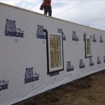
If lumber gets too wet, it can shrink and warp as it dries and cause cracks in the attached drywall.  This shrinking and warping can also make it difficult to properly insulate. To decrease  risks of potential moisture problems, ensure exteriors are covered with an appropriate and well-sealed Weather Resistant Barrier and lumber is properly dried before drywall and insulation are installed.

Another drawback of a stick built home is it usually takes several weeks to complete framing.  Total amount of time it will take will obviously depend on size and complexity of house plans and size, experience and availability of any particular framing crew.

A framing crew must precisely cut, assemble and erect barndominium framing components sometimes in adverse weather conditions.  Working around adverse weather conditions is another challenge with stick framing.

Although site-built, stick framed homes clearly dominate America’s housing market, there are several other ways to build a barndominium’s structure. These include post frame, PEMB (pre-engineered metal buildings), weld up steel and concrete.

Cross Bucks on Sliding Barn Doors

Many iconic traditional wooden barns feature sliding doors with wooden cross bucks.
Originally, the cross buck design had a utilitarian purpose, fortifying gates, fences, and large barn doors by providing structural support. However, the X-design on doors appeared in the mid-1800s as part of what was called “Stick Style.” This Gothic-inspired variation of Victorian architecture was a bit less fanciful and ornamental, highlighting instead the barn’s structure and construction through the application of “stick work” in the form of vertically and diagonally placed wood boards.

No one happens to manufacture a prefabricated cross buck for steel covered sliding doors. Over the years I have seen almost as many solutions for sliding door cross bucks as there are people who wanted them. Here are a few of them:

The simple way – use masking tape to mark off the width of cross buck desired, then spray paint them on. The downsides are this does not give a three dimensional look and there is a good chance of the paint peeling off over time.

Order flat steel trims with hems on both sides and screw onto each high rib with metal-to-metal stitch screws. Again this does not give the three dimensional look. Even with the hems, these are prone to “oil can” (look wavy) with changes in temperature. In most instances, these trims are limited to lengths of usually 10’6″ which can result in splices, which may not be desirable.

Dimensional lumber (I would recommend it be pressure preservative treated) can be attached to the face of the steel siding. U shaped steel trim, bent to fit the lumber, with hems on both of the short legs can be used to cover the lumber. This will give the three dimensional look, however will still present some of the same challenges as did the flat steel trims.


Are My Columns Too Short?

Are My Columns Too Small or Too Short?

We receive and answer lots of questions. Even with a Construction Guide which extends over 500 pages, covering a plethora of topics and how to’s, there is always an unanswered question (sometimes two).

One of our good clients recently sent a query to the Hansen Pole Buildings’ wizardess of all things shipping, Justine, which I share now:

“Hi Justine, I received delivery of the columns for my building on Friday. After inspection, I had 2 questions that I’m hoping you can clarify for me because I don’t know if there is an issue with them. I also want to apologize in advance, because I know these questions are pedantic and probably nothing to worry about, I just want to make sure there’s no problem here since I haven’t been involved with the kind of construction that requires inspections before. 🙂

The building plans seem to have a slightly larger dimension than what was delivered. I’m sure the engineering has allowed enough safety margin that this won’t be a problem, I just don’t know if it’s going to be an issue on an inspection. For example, the corner columns are shown on the blueprints at 5 3/8″ x 4 1/8″ but the columns that were delivered are 5 1/4″ x 4 1/8″. So, you see it’s only 1/8″ on the long dimension of the column, but I don’t know if an inspector will have a problem with that. The same 1/8″ undersize dimension is true on the corner, endwall, sidewall, and shed columns.

I was under the impression that the length of the columns was a minimum length and not a nominal length that might be slightly less than that. It could also be that I have a misunderstanding about how the columns are spec’d. What I found is that the 14′ columns are all actually 14′ 1″, which is great, however all of the 24′ columns are actually only 23′ 10 1/4″ when measured to the shortest of the three laminated boards. They are all right at 24′ when measured to the longest of the laminated boards. This is only a concern of mine because I’m in the process of getting the site leveled out, but I’m currently at about 12″, which is cutting things pretty close on some of the columns. So, I didn’t know if the manufacturer made a mistake or if I just need to correct the way I measure them. My main concern is around ensuring I have full weight bearing on the notched post, which will only happen if I notch them at least 11″ down. I’ve attached a photo to show how I’m measuring them.”
To which our Technical Support Department cheerfully responded:

Thank you very much for sending us your concerns.

#1 You are going to find the dimensional lumber (2×4 through 2×12) provided can vary as much as 1/4″ plus or minus from the anticipated “ideal” dimensions. It is part of the randomness of dealing with an organic product (wood) which has to be milled. It is also why we are only able to use 40% of Pult (the ultimate strength of a material in a wood assembly) when engineering calculations are produced. In looking at the calculations for the long columns in the center of your building, for example, they are stressed to 92% using the “call out” dimensions. Using a Sm (Section modulus – depth of lumber squared x width of lumber divided by 6) of the 1/8″ under size, reduces the actual Sm by 1.64%, which would mean the member would be stressed to 94% under maximum design load.

#2 Column lengths do vary slightly due to the material lost in finger jointing. On the 20′ eave raised center section, with the bottom of the column at 32″ below grade, the amount of column needed would be 22’8″. With a column length of 23’10-1/4″ you could have as much as 13-3/4″ of grade change and still have plenty of column.

If you do happen to have a foot of grade change, it would be my recommendation to have the site brought closer to level before setting columns. Good compactable fill is not inexpensive. Reducing the grade change from 12″ to say four inches, as an example, saves 27 yards of fill across just the footprint of your building.

Please do not hesitate to reach out to this department further with any technical questions.