Tag Archives: bearing blocks

Creating Extra Work in Barndominium Framing

Creating Extra Work In Barndominium Framing

A supposed downside of post frame (pole barn) buildings for barndominiums is having to frame a wall inside of an exterior wall in order to create an insulation cavity and a way to support interior finishes.

This myth is created and propagated by post frame kit suppliers and post frame builders who do not understand there is a solution – and a very cost effective one (in both labor and materials).

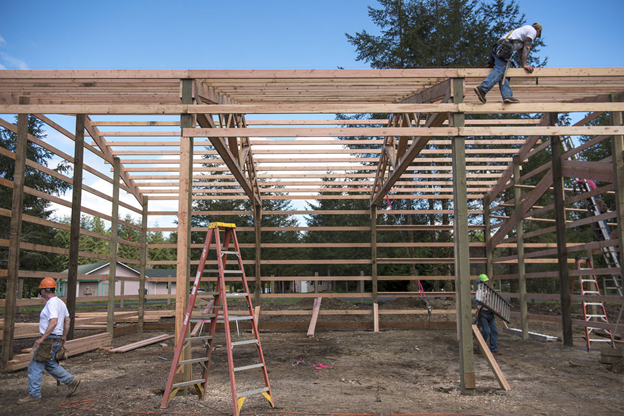
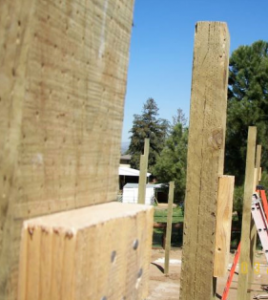
Rather than framing exterior girts (as shown in photo) and then adding vertical stud walls between columns, bookshelf girts can be utilized.

I’ve done several thousand pole buildings using this “bookshelf” or “commercial” girt method. I have two of them myself – in Northeastern WA, so I have a cold climate to contend with.

Use a commercial girt one size larger than wall columns (2×8 on a 6×6 post, etc.), setting commercial girts so 1-1/2″ hangs past the column’s exterior face. Wrap framing with a well sealed high quality Weather Resistant Barrier (for extended reading on Weather Resistant Barriers https://www.hansenpolebuildings.com/2016/01/determining-the-most-effective-building-weather-resistant-barrier-part-1/). 

As an alternative to using a Weather Resistant Barrier, closed cell spray foam can be applied to the interior face of siding as part of a flash-and-batt system https://www.hansenpolebuildings.com/2020/01/flash-and-batt-insulating-barndominium-walls/.

You will find this installation method compensates for any irregularities in column dimensions and creates a deeper insulation cavity. Side benefits – electrical can be run around column exteriors, without a need to drill through them to run wires. On walls a multiple of three feet in length, it also saves having to rip an edge of a panel off either the first or last sheet of steel on a wall.

In either case, block ends of bookshelf commercial girts solid against columns with what is called a “bearing block”.  Take 2×4’s or larger (depends upon engineering) cut 22-1/2” long to fit between commercial girts and install them flat against the post on faces where girts will attach.  Wide face of the block should be flat against the column and aligned with the post edge (not sticking out past column edge unlike girts).   Nail these girt support blocks to columns with a minimum of  two (2)10d galvanized common nails at each end (higher wind loads may require more nails).  This type of nailing is quick and easy and provides a solid support for commercial girt above blocks.  This is a far more solid and stable connection than toe-nailing. Toe-nailing is done by angling a nail upwards from bottom (or downwards from top) of commercial girt, at a 45 degree angle trying to catch enough post edge as the nail goes through to column to hold it there.  Toe-nailing is a very poor connection (and is subject to lots of installation errors).

For maximum cost effective R value, use BIBS insulation. I found it to be cost competitive with installed batt insulation, has a higher R value and completely fills all voids. https://www.hansenpolebuildings.com/2011/11/bibs/

I fondly remember a gal who called me one day asking for “canning jar shelves”…you know like you did before for us.”  Checking our records, I quickly discovered we designed commercial girts on their first building.  They liked them so much – they wanted them again!

Structural Screws? Pine or Spruce? and How Many Windows?

Today’s Pole Barn Guru addresses questions regarding structural screws for bearing blocks, the strength of pine vs spruce, and adding more windows than plans indicate.

DEAR POLE BARN GURU: How many structural screws should I use in a bearing block for supporting a 2×12 rafter? KENT in OTIS ORCHARDS

DEAR KENT: In case you were unaware, Otis Orchards and several surrounding communities were originally part of a land swindle scheme. Marketed to Easterners with picturesque names such as Otis Orchards, Veradale and Opportunity practically untillable land was sold sight unseen. Those folks were mightily disappointed to find this area as being pretty much high desert gravelly soil covered with glacial moraine!

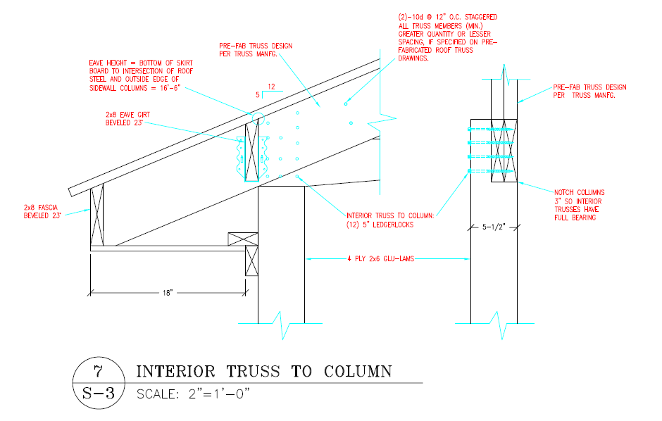
Back to your question – this connection (as well as all connections for your building) should be detailed on engineered plans provided for your building. Actual number required will be determined by your engineer by calculating imposed wind and snow loads upon this connection, resisted by screws’ holding power. A structural screw’s load capacity will be affected by species of lumber being used as well as depth of penetration into members and direction loads are being applied.

If this has not been addressed on your plans, you need to contact either your engineer or whomever provided you with your building kit package.


DEAR POLE BARN GURU: Could you give me a link or tell me pros and cons of using Pine or Spruce? Half of the load of lumber I ordered is warped, bowed, not usable for purlins. I am considering spruce if it is ok for 10’ and 12’spans. Thank you CALEB in TEXAS

DEAR CALEB: I personally prefer working with SPF (Spruce) as opposed to SYP (Southern Yellow Pine). SYP tends to warp and twist very quickly and is more difficult to drive nails and screws into. SPF is stronger than SYP of an equal grade. You will want to confirm it being okay with your engineer who designed your building plans.


DEAR POLE BARN GURU: I’m wondering about the windows, if we want a lot more than you provide, how are they added in? Is it structurally sound to have walls of windows? MEGAN

DEAR MEGAN: All openings, including windows need to be considered and placed in your third-party independently engineer sealed plans provided with your post frame building kit. While you can have a large number of windows (or openings) in a wall, they do need to be accounted for.


Connecting Trusses Not Dots

Connecting Trusses Not Dots

This feature is probably not overly mentioned, however as most structural failures involve connections, it probably should be.

FEATURE: Double trusses notched into sidewall columns and connected with Strong-Drive® SDWS TIMBER Screws

BENEFIT: Trusses placed in a notch cannot slide down columns and Strong-Drive® SDWS TIMBER Screws resist uplift forces without a need for boring holes through columns.

WHAT OTHERS DO: A myriad of design solutions exist.

For trusses mounted every two or four feet upon truss carriers (headers between sidewall columns) attachment can be by toe-nail or engineered steel hangers to carriers. In some instances paddle blocks are inserted between carriers and trusses are nailed to these blocks.

With single trusses aligned with sidewall columns, trusses are most often placed into a notch cut into one side of columns. With nail or glu-laminated columns an interior column ply can be cut short to create an integral notch. Truss to column connections may include nails and/or bolts.

In designs with two single trusses, most often a truss is placed on each side of sidewall columns on top of bearing blocks. Bearing blocks may be nailed, lagged or bolted to column sides. Trusses are attached in same fashion as bearing blocks. Trusses are spaced apart along their length by paddle blocking installed between chords. Under extreme loading conditions trusses and their bearing blocks have been seen driven down sides of columns to rest upon building contents or even, the ground.

A variant on this places trusses closer together so they may be notched into sides of each column. This allows for elimination of bearing blocks and their associated challenges.

At Hansen Pole Buildings, we have trusses physically face-to-face nailed providing for a true load sharing between trusses. A notch is cut into one side of columns for trusses to bear. Attachment of trusses to columns is most often done by use of Strong-Drive SDWS Timber screws.

WHAT WE DID IN 1980: Lucas Plywood & Lumber placed a single truss upon each side of columns, on top of a nailed on bearing block. Trusses were attached to columns by means of a ¾” diameter, non-galvanized through bolt – entailing having to drill through nearly nine inches of wood and hoping to avoid steel connector plates at each truss heel.


Spot the Post Frame Problem

Spot The Post Frame Problem – Reprised

In our last episode, I left you all with a cliff hanger. I did clue you into it being a structural issue, which rules out our builder in the air with his safety harness hooked to an invisible sky hook.
While you all ponder the photo and look at it closely, I will mention a few items which are not necessarily a problem, just maybe not what I would call “best practices”.

Note the trusses. One is on each side of the column. Chances are good this builder is marketing his product as a double truss system. What they actually have are two single trusses spaced 5-1/2 inches apart. These trusses do not act as a pair, because the blocking between them will not transfer the load from one truss to the other.

Each of those trusses is bearing on a block. The trusses are depending only upon the nails or bolts driven through the end of the truss and the blocks to keep them up in the air. There was a time when I did buildings this way also. Until the day I saw a set of trusses and the blocks below them driven down the sides of the poles by excess snow! They were only stopped from hitting the ground by the vehicles which were crushed inside.

Paddle blocks – if you do not know what they are, or their potential for future challenges, you will want to read here: https://www.hansenpolebuildings.com/2012/05/paddle-blocks/.
Okay, time to get serious here. Look at all the pretty wall girts. Nailed flat on the outside of the columns. They all fail due to not meeting the required deflection criteria set by the Building Codes: https://www.hansenpolebuildings.com/2012/03/girts/.

Now the particular jurisdiction where this building is being built has their own prescriptive solution to this problem. I’ve railed against prescriptive requirements in this forum previously: https://www.hansenpolebuildings.com/2012/02/prescriptive-requirements/. Look closely at the wall in the back of the photo. Look at the right hand bay. Note how every other wall girt has another board nailed to it to form an “L” as a stiffener. Truly wonderful as this solves the deflection issue for these particular girts only. The girt in between, without the stiffener, still fails!

Again I preach and beseech – please, if you are going to construct or have constructed for you a new post frame building, only do so with plans which are design specifically for your building and your building only, which are designed by a Registered Design Professional (architect or engineer).