Code Requirements for Residential Roof Trusses
Reprinted from a March 2019 article in Structure Magazine authored by Brent Maxfield, P.E.
Part 3 of 3:
 Implementation
1. Building Officials, Contractors, Owners, and Building Designers should be cognizant of and enforce the requirement that the Contractor and the Building Designer review the Truss Submittal Package prior to the installation of the Trusses. Building Officials should establish procedures to ensure that this code requirement is followed.
2. Many engineering drawings have general notes that require the Trusses to be designed and stamped by a registered engineer. It is important to understand that the stamp is for individual Trusses and not for the Trusses acting together as a system. Many engineers falsely assume that this stamp is for the individual Trusses as well as for the roof system.
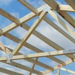
3. Truss web bracing locations are provided on the Truss Design Drawings in the Truss Submittal Package. The BCSI document usually provides the bracing details. Many Truss webs do not align with adjacent Trusses, making continuous Lateral Restraint
bracing impossible to install. In these cases, T or L bracing will be required. Construction Documents should provide details and instructions for when T or L bracing is required.
4. Truss web bracing is critical to the stability of the roof system, yet very few residential projects have engineering observation of completed roof systems. Unless the Truss spans 60 feet or more, special inspection of the Truss web bracing installation is not required. This is an area where the code requirements could be improved.
5. Many projects have general notes that state that snow drift and unbalanced snow loading are required to be considered in the Truss design, but the Construction Documents do not provide the actual values of the snow drift loads and the unbalanced loads for each Truss. This is contrary to ANSI/TPI 1, Section 2.3.2.4(d). It is important to understand that the responsibility for calculating and providing the loads applied to each Truss rests with the Building Designer.
6. A functioning roof system is the responsibility of the Building Designer and consists of Trusses, bracing, blocking, connections to structure, diaphragms, and an understanding of the load path of all forces. The Truss Submittal Package is only one piece of the system.
7. If a portion of the roof system falls outside of the scope of the IRC, then that portion, including the associated load paths, will require engineering analysis. If the Building Designer is not an engineer, then an engineer who is not filling the role of the Building Designer could be engaged for a limited scope to design and stamp the elements that fall outside of the scope of the IRC.
 This article intends to educate engineers about the roles and division of responsibilities for residential wood Trusses. It is critical to understand the specific scope of the Truss Designer as defined in ANSI/TPI 1. The Truss Designer is responsible for individual Truss Design Drawings using loading information obtained from the Truss Manufacturer, who gets information from the Contractor in the form of selected information from the Construction Documents. The Building Designer is responsible for ensuring that the Truss loads given to the Truss Designer are accurate. The Building Designer is also responsible for ensuring that all Trusses act together as a roof system. All players need to understand and fulfill their responsibilities as outlined in ANSI/TPI 1 in order to achieve a safe and code-conforming building.
 A classic example of this came when International Building Codes were first adopted in 2000. Prior Codes did not have deflection criteria for wall members in those cases where members did not support a rigid finish (like plaster or gypsum board). New Code limits deflection for all instances. In order to meet these new requirements, in many cases, pole building wall girts can no longer be installed “flat” on wall column exteriors.
 Now ignorance is bliss and some folks, well they are very, very happy. Legally (not to mention morally) an engineered set of building plans cannot be customized, without a revised set of engineered drawings being produced. An engineer puts his or her career on the line when they seal a set of drawings – it does not come with free rein to make any changes!
 Tornado damage in Jefferson City, Mo. as seen on Thursday, May 23, 2019. Photo by David Carson, St. Louis Post-Dispatch.
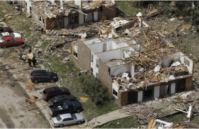 The entire construction industry can greatly benefit by staying focused on providing framer-friendly details that are easy to understand and implement. It’s critical that we come together with the goal of fostering innovation, using accepted engineering practice, creating installation best practices, working closely with professional framers and assisting building departments to focus inspections on key load path elements. We all are educators. By working together, we will significantly improve the built environment.”
 To help address the design challenges associated with high wind, this week the American Wood Council (AWC) published a series of updated Guides to Wood Construction in High Wind Areas. The guides are based on provisions contained in AWC’s 2012 Wood Frame Construction Manual (WFCM), and establish a specific set of prescriptive, wind-resistive structural requirements for wood-frame buildings in compliance with the 2012 International Building Code (IBC) and International Residential Code (IRC).
 The mean roof height would be the average of 12’ plus 22.67’ or 17.33’ as shown on the building plans. It appears there may have been some confusion, on the client’s part, as to the definition of “mean roof height”.


