This week the Pole Barn Guru answers questions about the footing size for an open car porch and why a person should use a registered design professional, building a “reverse barndominium” where one build a post frame shell around an existing structure, and if one can build a loft bedroom in a footprint of 20’x 30′.
 DEAR POLE BARN GURU: I am building an open car porch, the inside will be connected to another building and on the outside I planning on using 3 – 8 inch x 8 inch x 8 feet posts 12 feet apart. The open car porch area is 24ft x 24ft and the roof is 6 on 12 with 2 x 6 rafters and joists landing on the outside plate. What size footing will I need for each pole? JAY in MORGAN CITY
DEAR JAY: This is a question best answered by the Registered Professional Engineer who designed your building, as he or she will be able to do a complete analysis including soil bearing capacity, design wind speed and wind exposure. With columns only eight feet long, I am guessing you are planning on using wet set brackets into concrete piers https://www.hansenpolebuildings.com/2019/05/sturdi-wall-plus-concrete-brackets/. I would not be surprised to see piers up to three feet deep and two foot diameter in order to adequate resist uplift forces.
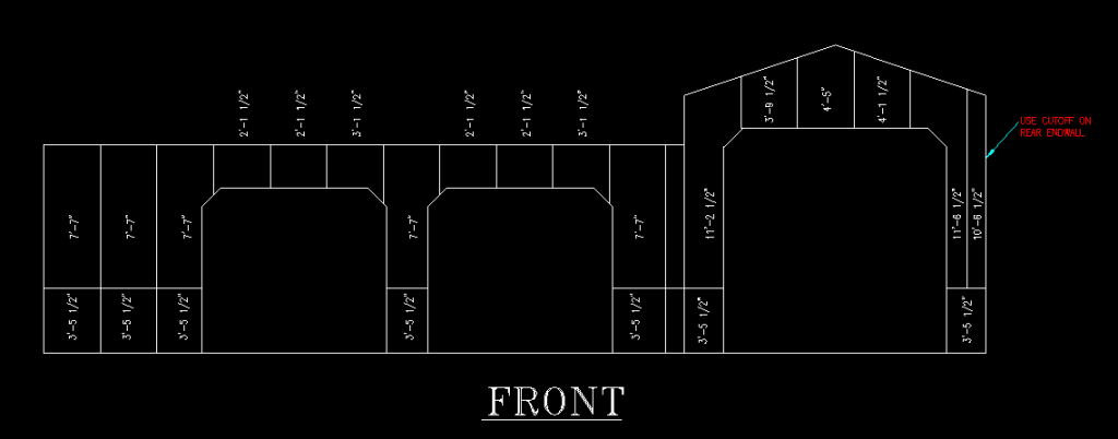
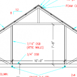
DEAR POLE BARN GURU: Are you aware of anyone ever building a “reverse barndominium”? Usually barndominiums are built shell (outside walls) first then the interior, but what about building entirely around an existing structure? I really want to buy this historic house built in 1861. It is currently gutted down to the dirt floors, needs a roof, garage, etc. Why not just enclose the whole thing and DIY the interior without dealing with the outside elements? The primary structure is 19’x38′, but the side structure is an additional 20′ (39′ total wide) with a 6/12 roof. The eave height is 15.5′ and about 20′ at the ridge. The basement is about 4′ deep. I could go 42′ wide with a structure and have the exterior posts completely outside of the current footprint. The lot is 60’x150′ and I’m looking at a 40×80-ish building with a second story.
Is this feasible or have I succumb to the Dunning-Kruger Effect? I have attached an image of my sketchup drawing to give a better idea of my concept.
Thank you great guru. I love your philosophy and transparency throughout your blog posts. I have learned a lot at the cost of otherwise being productive at work. JAMES in WESTON
DEAR JAMES: Thank you very much for your kind words, although I am not as certain your employer would be as happy with me 🙂
Perhaps surprisingly, you would be far from the first person to attempt such a project. Is is entirely doable and actually becomes very similar to what people do with a PEMB (Pre-engineered metal building aka red iron) or a weld up barndominium, where a shell is erected and a building is built inside of a building. You just happen to have your insides prebuilt!

Outside of my loyal readers, most have never heard of the Dunning-Kruger Effect (https://www.hansenpolebuildings.com/2015/01/dunning-kruger-effect/)
 DEAR POLE BARN GURU: I’m interested in a residential building approximately 20ft x 30ft. How tall would the walls need to be to include a loft bedroom with headspace to approximately 4ft from the sides? JUDE in DUPONT
DEAR JUDE: I will answer your question from a standpoint of you getting best value for your investment – meaning using both floors from wall to wall.
Assuming a concrete slab-on-grade for main level, bottom of framed ceiling would be at 8′ 4-5/8″ this allows for 5/8″ drywall on ceiling and 1/2″ at bottom to be able to account for any variances in your building slab and to keep drywall from soaking up moisture from floor, plus 3-1/2″ for actual thickness of a nominal four inch thick slab.
 I would recommend using premanufactured wood floor trusses between floors (https://www.hansenpolebuildings.com/2014/09/floor-trusses/). Plan on a 20 inch thickness, plus 3/4″ for subflooring and 8′ 1-1/8″ putting bottom of roof trusses at 18′ 2-1/2″. In Pennsylvania I would recommend R-60 blown in attic insulation (just under 20 inches thick), resulting in needing a 20 foot eave height.
 The challenge of any of these support methods is deflection. Even in areas with no snow, the support for the door or doors is going to deflect (sag) even under just the weight of the roof being carried and the weight from the door. We recently provided a hangar with a full hipped roof in the Carolinas, where the building owner was originally distressed to find the beam for his door deflected significantly (albeit within Code and sound engineering practice limitations).