How Far Can a 2×6 Purlin Span?
Reader WILL in COMFORT writes:
“How far can a 2×6 purlin on a 6:12 sloped roof span?”
 The following describes 2×6 SYP #2 purlins spanning a 14′ bay, with an on-center spacing of 24″ (sf).
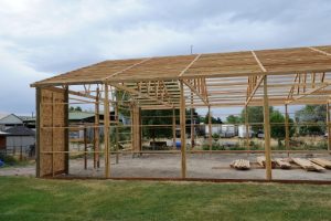
Purlins are recessed between rafters with their top edges flush with rafter top edges. Purlins are mounted to rafters with Simpson Strong-Tie LU-26 joist hangers at both ends.
Effective simple beam span length (le) will be taken as 165.
Applied loads
Dead load, D[
Dpurlin: dead load from weight of purlin itself
Dpurlin = purlin density × ((b × d × le) / (sf × l))
Purlin density found via NDS Supplement 2015 Section 3.1.3:
density = 62.4 × (G / (1 + (G × 0.009 × moisture content))) × (1 + (moisture content / 100))
moisture content = 19%
density = 62.4 × (0.55 / (1 + (0.55 × 0.009 × 0.19))) × (1 + (0.19 / 100))
density = 34.56 pcf
Dpurlin = 34.56 pcf × ( ( 1.5″ × 5.5″ × 165″ ) / ( 24″ × 168″ ) ) × 1/12 in/ft
Dpurlin = 0.966 psf
Roof designed for 29g corrugated steel
Dead load from weight of steel (Dsteel) based on values from the American Building Components catalogue:
Dsteel = 0.63 psf
D: dead load
D = Dpurlin + Dsteel
D = 0.966 psf psf + 0.63 psf psf
D = 1.596 psf
Project load to a vector acting perpendicular to the roof plane:
D = D × cos(Θ)
D = 1.596 psf × cos(0.464)
D = 1.428 psf
A conversion from psf to psi will be made for ease of calculation:
D = 1.428 psf × 1/144 psi/psf
D = 0.01 psi
Roof live load, Lr
L: roof live load
Lr = 18 psf
Project load to a vector acting perpendicular to the roof plane:
Lr = Lr × cos(Θ) × cos(Θ)
Lr = 18 psf × cos(0.464) × cos(0.464)
Lr = 14.4 psf
A conversion from psf to psi will be made for ease of calculation:
Lr = 14.4 psf × 1/144 psi/psf
Lr = 0.1 psi
Snow load, S
S: snow load
S = 13.267 psf
Project load to a vector acting perpendicular to the roof plane:
S = S × cos(Θ) × cos(Θ)
S = 13.267 psf × cos(0.464) × cos(0.464)
S = 10.614 psf
A conversion from psf to psi will be made for ease of calculation:
S = 10.614 psf × 1/144 psi/psf
S = 0.074 psi
Wind load, W
W: wind load
W = 9.6 psf
A conversion from psf to psi will be made for ease of calculation:
W = 9.6 psf × 1/144 psi/psf
W = 0.067 psi
Wind uplift load, Wu
Wu: wind uplift load
Wu = -11.763 psf
A conversion from psf to psi will be made for ease of calculation:
Wu = -11.763 psf × 1/144 psi/psf
Wu = -0.082 psi
Lr ≥ S, so roof live loads will dictate in load combinations.
Bending test (fb / Fb′ ≤ 1.0)
Fb: allowable bending pressure
Fb′ = Fb × CD × CM × Ct × CL × CF × Cfu × Ci × Cr
CL = 1
CM = 1 because purlins are protected from moisture by roof
Ct = 1 NDS 2.3.3
CF = 1 NDS Supplement
Ci = 1 NDS 4.3.8
Cr = 1 NDS 4.3.9
S: section modulus
S = (b × d2) / 6
S = (1.5″ × (5.5″)2) / 6
S = 7.563 in3
w: pounds force exerted per linear inch of beam length
M: maximum moment
fb: maximum bending stress
Load combinations:
- D
CD = 0.9
Cfu = 1
Fb′ = 1000 psi × 0.9 × 1 × 1 × 1 × 1 × 1 × 1 × 1
Fb′ = 900 psi
w = (D) × sf
w = 0.008 psi × 24″
w = 0.186 pli
M = (w × l2) / 8
M = ( 0.18559992381479 pli × (165″)2 ) / 8
M = 654.797 in-lbs
fb = M / S
fb = 654.797 in-lbs / 7.563 in3
fb = 86.585 psi
fb / Fb′ ≤ 1.0
86.585 psi / 900 psi ≤ 1.0
0.096 ≤ 1.0
- D + Lr
CD = 1.25
Cfu = 1
Fb′ = 1000 psi × 1.25 × 1 × 1 × 1 × 1 × 1 × 1 × 1
Fb′ = 1250 psi
w = (D + Lr) × sf
w = 0.108 psi × 24″
w = 2.586 pli
M = (w × l2) / 8
M = ( 2.5855999238148 pli × (165″)2 ) / 8
M = 9121.997 in-lbs
fb = M / S
fb = 9121.997 in-lbs / 7.563 in3
fb = 1206.214 psi
fb / Fb′ ≤ 1.0
1206.214 psi / 1250 psi ≤ 1.0
0.965 ≤ 1.0
- D + W
CD = 1.6
Cfu = 1
Fb′ = 1000 psi × 1.6 × 1 × 1 × 1 × 1 × 1 × 1 × 1
Fb′ = 1600 psi
w = (D + W) × sf
w = 0.074 psi × 24″
w = 1.786 pli
M = (w × l2) / 8
M = ( 1.7855999238148 pli × (165″)2 ) / 8
M = 6299.597 in-lbs
fb = M / S
fb = 6299.597 in-lbs / 7.563 in3
fb = 833.004 psi
fb / Fb′ ≤ 1.0
833.004 psi / 1600 psi ≤ 1.0
0.521 ≤ 1.0
- D + Wu
CD = 1.6
Cfu = 1
Fb′ = 1000 psi × 1.6 × 1 × 1 × 1 × 1 × 1 × 1 × 1
Fb′ = 1600 psi
w = (D + Wu) × sf
w = -0.074 psi × 24″
w = -1.775 pli
M = (w × l2) / 8
M = ( -1.7748379435325 pli × (165″)2 ) / 8
M = -6261.628 in-lbs
fb = M / S
fb = -6261.628 in-lbs / 7.563 in3
fb = -827.984 psi
fb / Fb′ ≤ 1.0
-827.984 psi / 1600 psi ≤ 1.0
-0.517 ≤ 1.0
- D + 0.75Lr + 0.75W
CD = 1.6
Cfu = 1
Fb′ = 1000 psi × 1.6 × 1 × 1 × 1 × 1 × 1 × 1 × 1
Fb′ = 1600 psi
w = (D + 0.75Lr + 0.75W) × sf
w = 0.133 psi × 24″
w = 3.186 pli
M = (w × l2) / 8
M = ( 3.1855999238148 pli × (165″)2 ) / 8
M = 11238.797 in-lbs
fb = M / S
fb = 11238.797 in-lbs / 7.563 in3
fb = 1486.122 psi
fb / Fb′ ≤ 1.0
1486.122 psi / 1600 psi ≤ 1.0
0.929 ≤ 1.0
- D + 0.75Lr + 0.75Wu
CD = 1.6
Cfu = 1
Fb′ = 1000 psi × 1.6 × 1 × 1 × 1 × 1 × 1 × 1 × 1
Fb′ = 1600 psi
w = (D + 0.75Lr + 0.75Wu) × sf
w = 0.021 psi × 24″
w = 0.515 pli
M = (w × l2) / 8
M = ( 0.51527152330431 pli × (165″)2 ) / 8
M = 1817.878 in-lbs
fb = M / S
fb = 1817.878 in-lbs / 7.563 in3
fb = 240.381 psi
fb / Fb′ ≤ 1.0
240.381 psi / 1600 psi ≤ 1.0
0.15 ≤ 1.0
Purlin stressed in bending to a maximum of 96.5%
Shear test (fv / Fv′ ≤ 1.0)
Fv: allowable shear pressure
Fv′ = Fv × CD × CM × Ct × Ci
CM = 1 because purlins are protected from moisture by roof
Ct = 1 NDS 2.3.3
Ci = 1 NDS 4.3.8
V: max shear force
fv: max shear stress
Load combinations:
- D
CD = 0.9
Fv‘ = 175 psi × 0.9 × 1 × 1 × 1
Fv‘ = 157.5 psi
V = w × (le – (2 × d)) / 2
V = 0.186 pli × ( 165″ – (2 × 5.5″) ) / 2
V = 14.57 lbs
fv = (3 × V) / (2 × b × d)
fv = (3 × 14.57 lbs) / ( 2 × 1.5″ × 5.5″ )
fv = 2.649 psi
fv / Fv′ ≤ 1.0
2.649 psi / 157.5 psi ≤ 1.0
0.017 ≤ 1.0
- D + Lr
CD = 1.25
Fv‘ = 175 psi × 1.25 × 1 × 1 × 1
Fv‘ = 218.75 psi
V = w × (le – (2 × d)) / 2
V = 2.586 pli × ( 165″ – (2 × 5.5″) ) / 2
V = 202.97 lbs
fv = (3 × V) / (2 × b × d)
fv = (3 × 202.97 lbs) / ( 2 × 1.5″ × 5.5″ )
fv = 36.904 psi
fv / Fv′ ≤ 1.0
36.904 psi / 218.75 psi ≤ 1.0
0.169 ≤ 1.0
- D + W
CD = 1.6
Fv‘ = 175 psi × 1.6 × 1 × 1 × 1
Fv‘ = 280 psi
V = w × (le – (2 × d)) / 2
V = 1.786 pli × ( 165″ – (2 × 5.5″) ) / 2
V = 140.17 lbs
fv = (3 × V) / (2 × b × d)
fv = (3 × 140.17 lbs) / ( 2 × 1.5″ × 5.5″ )
fv = 25.485 psi
fv / Fv′ ≤ 1.0
25.485 psi / 280 psi ≤ 1.0
0.091 ≤ 1.0
- D + Wu
CD = 1.6
Fv‘ = 175 psi × 1.6 × 1 × 1 × 1
Fv‘ = 280 psi
V = w × (le – (2 × d)) / 2
V = -1.775 pli × ( 165″ – (2 × 5.5″) ) / 2
V = -139.325 lbs
fv = (3 × V) / (2 × b × d)
fv = (3 × -139.325 lbs) / ( 2 × 1.5″ × 5.5″ )
fv = -25.332 psi
fv / Fv′ ≤ 1.0
-25.332 psi / 280 psi ≤ 1.0
-0.09 ≤ 1.0
- D + 0.75Lr + 0.75W
CD = 1.6
Fv‘ = 175 psi × 1.6 × 1 × 1 × 1
Fv‘ = 280 psi
V = w × (le – (2 × d)) / 2
V = 3.186 pli × ( 165″ – (2 × 5.5″) ) / 2
V = 250.07 lbs
fv = (3 × V) / (2 × b × d)
fv = (3 × 250.07 lbs) / ( 2 × 1.5″ × 5.5″ )
fv = 45.467 psi
fv / Fv′ ≤ 1.0
45.467 psi / 280 psi ≤ 1.0
0.162 ≤ 1.0
- D + 0.75Lr + 0.75Wu
CD = 1.6
Fv‘ = 175 psi × 1.6 × 1 × 1 × 1
Fv‘ = 280 psi
V = w × (le – (2 × d)) / 2
V = 0.515 pli × ( 165″ – (2 × 5.5″) ) / 2
V = 40.449 lbs
fv = (3 × V) / (2 × b × d)
fv = (3 × 40.449 lbs) / ( 2 × 1.5″ × 5.5″ )
fv = 7.354 psi
fv / Fv′ ≤ 1.0
7.354 psi / 280 psi ≤ 1.0
0.026 ≤ 1.0
Purlin stressed in shear to a maximum of 16.9%
Deflection test (Δmax / Δallow ≤ 1.0)
I: moment of inertia
I = b × d3 / 12 NDS 3.3.2
I = ( 1.5″ × (5.5″)3 ) / 12
I = 20.797 in4
E: modulus of elasticity
E′ = E × CD × CM × Ct × Ci
CM = 1 because purlins are protected from moisture by roof
Ct = 1 NDS 2.3.3
Ci = 1 NDS 4.3.8
Δallow: allowable deflection
Δmax: maximum deflection
Load combinations:
- D + Lr
CD = 1.25
E′ = 1400000 × 1.25 × 1 × 1 × 1
E′ = 1750000 psi
Per IBC 1604.3 footnote d, dead load may be taken as 0.5D.
w = ((0.5 × D) + Lr) × sf
w = ( (0.5 × 0.01 psi) + 0.1 psi ) × 24″
w = 0.104 pli
Δallow = l / 150 IBC 1604.3
Δallow = 165″ / 150
Δallow = 1.1″
Δmax = (5 × w × l4) / (384 × E′ × I)
Δmax = ( 5 × 2.493 pli × (165″)4 ) / ( 384 × 1750000 psi × 20.797 in4 )
Δmax = 0.661″
Δmax / Δallow ≤ 1.0
0.661″ / 1.1″ ≤ 1.0
0.601 ≤ 1.0
- D + W
CD = 1.6
E′ = 1400000 × 1.6 × 1 × 1 × 1
E′ = 2240000 psi
Δallow = l / 150 IBC 1604.3
Δallow = 165″ / 150
Δallow = 1.1″
Δmax = (5 × w × l4) / (384 × E′ × I)
Δmax = ( 5 × 1.786 pli × (165″)4 ) / ( 384 × 2240000 psi × 20.797 in4 )
Δmax = 0.37″
Δmax / Δallow ≤ 1.0
0.37″ / 1.1″ ≤ 1.0
0.336 ≤ 1.0
- D + Wu
CD = 1.6
E′ = 1400000 × 1.6 × 1 × 1 × 1
E′ = 2240000 psi
Δallow = l / 150 IBC 1604.3
Δallow = 165″ / 150
Δallow = 1.1″
Δmax = (5 × w × l4) / (384 × E′ × I)
Δmax = ( 5 × -1.775 pli × (165″)4 ) / ( 384 × 2240000 psi × 20.797 in4 )
Δmax = -0.368″
Δmax / Δallow ≤ 1.0
-0.368″ / 1.1″ ≤ 1.0
-0.334 ≤ 1.0
- D + 0.75Lr + 0.75W
CD = 1.6
E′ = 1400000 × 1.6 × 1 × 1 × 1
E′ = 2240000 psi
Δallow = l / 150 IBC 1604.3
Δallow = 165″ / 150
Δallow = 1.1″
Δmax = (5 × w × l4) / (384 × E′ × I)
Δmax = ( 5 × 3.186 pli × (165″)4 ) / ( 384 × 2240000 psi × 20.797 in4 )
Δmax = 0.66″
Δmax / Δallow ≤ 1.0
0.66″ / 1.1″ ≤ 1.0
0.6 ≤ 1.0
- D + 0.75Lr + 0.75Wu
CD = 1.6
E′ = 1400000 × 1.6 × 1 × 1 × 1
E′ = 2240000 psi
Δallow = l / 150 IBC 1604.3
Δallow = 165″ / 150
Δallow = 1.1″
Δmax = (5 × w × l4) / (384 × E′ × I)
Δmax = ( 5 × 0.515 pli × (165″)4 ) / ( 384 × 2240000 psi × 20.797 in4 )
Δmax = 0.107″
Δmax / Δallow ≤ 1.0
0.107″ / 1.1″ ≤ 1.0
0.097 ≤ 1.0
Purlin stressed in deflection to a maximum of 60.1%
 This is why concrete contractors are not allowed to engineer buildings (unless they have actually gone to school, passed their boards and gotten registered). As suggested, a large load is going to be placed upon your building’s columns along this wall, resulting possibly in larger columns, greater embedment depth and more concrete around columns. Throw in what you will invest in two sets of four foot high UC-4B pressure preservative treated tongue and groove lumber and you are talking some serious money.
 As far as your attic “storage” idea, be wary. By Building Code, light storage areas need to be designed for a 125 psf (pounds per square foot) live load. Even on a 22 foot truss span, these trusses are going to be expensive. Now you could designate this as a ‘bonus room’ and provided your Building Department buys into it, you could have a much lower live load (as little as 30 psf). You would need to remain mindful of what you were actually placing in this area, so as not to overload it and cause an unintended failure.
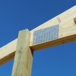 In my humble opinion, an ideal design solution eliminates need for a header (aka truss carrier) entirely, by having trusses bear directly upon columns. Why would this be ideal? Trusses (in my ideal dream world) are placed into a field cut notch in each column. This transmits all roof loads directly onto posts, without reliance upon beams typically scabbed onto each side. This eliminates trusses being driven to earth in a catastrophic snowfall event.
 Until I read their next paragraph:


