Tag Archives: Dr. Frank Woeste

Laminated Columns

What every post-frame builder should know about laminated columns

By Sharon Thatcher (Frame Building News January 2021)

The single most important element to a building’s foundation is its columns. They’re the legs that hold the building upright. As post frame has evolved, it’s only natural that methods to improve the strength of those legs would be part of its evolution.

For a comprehensive explanation of laminated columns, the second edition of the NFBA Post Frame Building Design Manual contains a chapter by David R. Bohnhoff, Ph.D., University of Wisconsin-Madison. Bohnhoff has been breaking columns in the name of science since the 1980s. In fact, he got the Ph.D. behind his name after writing his doctoral thesis on laminated columns, which led to the standards for design and manufacturing of mechanically laminated columns.

Frame Building News offers a more generalized explanation here, relying on NFBA members who have embraced the technology in manufacturing, along with other industry insiders.

There are many ways to laminate columns, but the industry keeps them confined into two basic categories: mechanical fastened (mechlam) and glue laminated (glulam). Mechlams utilize nails (a popular type of mechlam called nail-lam) and/or other mechanical fastener components (screws, bolts, and/or metal plates) while, as the name implies, glulam utilizes glue or a glue-like adhesive.


Bohnhoff’s chapter 8 clearly defines each and breaks down all the variations of mechlam. Because nail-lam and hybrid versions of nail-lam (including the use of both nails and glue) are the most recognized mechlam products in use today, this article makes use of the commonly used term “nail-lam.”

Arguments rage over which is best, but properly manufactured, both nail-lam and glulam trump solid-sawn timber in certified testing labs for consistency of strength, straightness, and uniformity of preservative treatment.

A glulam typically has good bending strength regardless of which column face is loaded, so it has advantages in applications in which the column does not have lateral support like that provided by wall girts. Such is the case with many interior columns and columns supporting the open side of a building. Nail-lam columns can be used in such applications, but typically need additional bracing such as faceplates to prevent buckling or bending around their weak axis.

The environmental and economical advantages of laminated columns were addressed in an article, “Engineered Wood Products STRETCH Post-Frame Possibilities” by Robert Clark, APA, Engineered Wood Association, which [at the time of publication was] housed on the NFBA website. “Engineered wood posts can use smaller diameter trees harvested from a managed forest dried to a low moisture content,” he wrote. “These dimensionally stable products resist deformations such as warping and twisting. And, because of the dispersal of natural growth characteristics such as knots and wane, they exhibit superior strength over solid-sawn posts.”


Just as today’s solid-sawn timbers, laminated columns are treated for preservation to endure the ravages of natural deterioration. While some manufacturers treat the entire finished post, many manufacturers treat the individual laminations prior to gluing or nailing. In this method, typically only the lower section of the post that will be installed in the ground is preservative-treated, which can be cost-effective and provide increased chemical coverage area at the interior of the post.

If you are considering the switch from solids to laminates, or you are questioning your choice of lamination, Dale Schiferl of Timber Technologies, Colfax, Wisconsin cautions: “Not all laminated columns are created equal.


“I have seen about a dozen different ways to ‘laminate’ a column in the past 20 years,” he said. “Everything from truss plates, to nails, to finger joints, to butt joints, to construction adhesive with nails, to gusset plates, to screws, to wire rivets, to bolts, and totally glue laminated. I have also seen a wide array of lumber utilized, from the highest grade of MSR and Select Structural lumber to the lowest grade and species of #2. Unlike other structural wood components, column manufacturing is like the Wild West, standards are not enforced. Basically everybody does what works best or cheapest for them.”

A lot of engineering goes into the proper design of laminated columns, Schiferl went on to note. “It should be important that specifiers and builders understand there are ‘standards’ to how columns are built up, be it nails or glue, and they ask for some verification that the products they are using follow the standards. The standards were established through testing by smart people like Dave Bohnhoff and Harvey Manbeck and through efforts of the NFBA. It does not make it OK to build up a column however one chooses just because the standards are not enforced,” he said.

Mike Burkholder, P.E., Ohio Timberland Products (OTP), Stryker, Ohio, echoes that sentiment. His company has been making nail-laminated columns for more than 20 years. Although he explained that, “there had been people nailing boards together for years,” Ohio Timberland Products began testing at Virginia State University in 1994 in the lab of Dr. Frank Woeste. By then, Bohnhoff was testing nail-lam and eventually created what Burkholder calls the “Bible” or “Genesis” of standards for the industry, but as far as developing its own production standards, OTP blazed its trail through the Woeste lab.

The price of laminated columns is one that arises on a daily basis for laminated column manufacturers like Elmer Sensenig, Richland Laminated Columns, Greenwich, Ohio.is articleblished in the January 2021 edition of F

“Laminated columns are very comparable [to solid-sawn columns],” he tells his customers. “For 20′ and longer, they’re actually less costly than a 6″ x 6″. The shorter you go, 14′ to 16′, the laminated columns are a little bit more.” Because builders typically need a combination of sizes, Sensenig stressed, “price is normally not an issue because it averages out.”

This article was published in the January 2021 edition of Frame Building News.

 Click to download the entire issue (free).

Christmas Morning 2017

Christmas Morning 2017

Christmas morning is traditionally when youngsters awaken their parent far too early – too see what surprises Santa has left them overnight.

On occasion there are surprises for adults as well – some of them not always as desired.

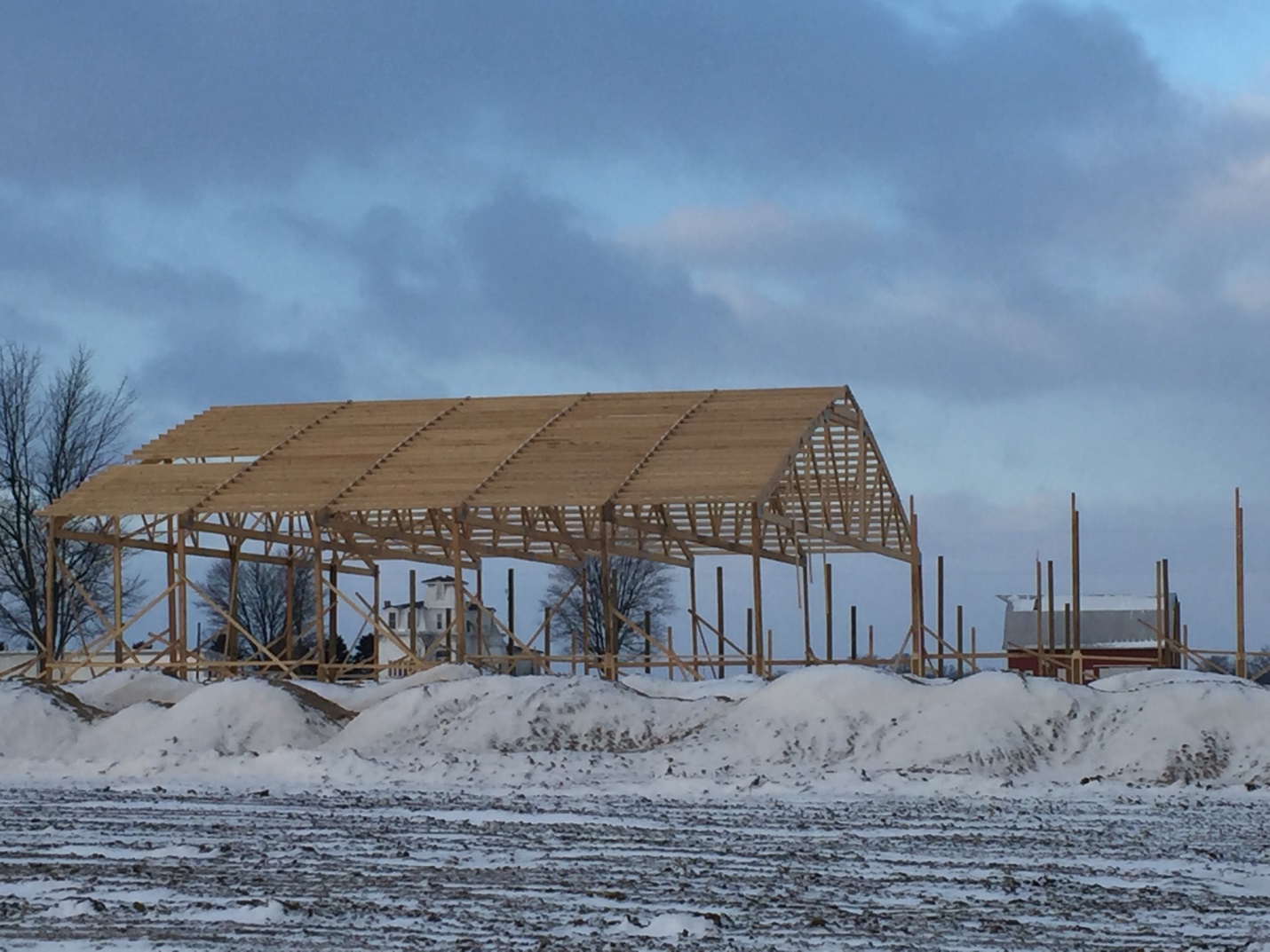
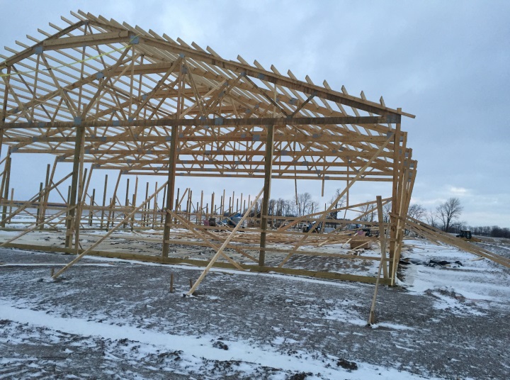
Below pictured are beginnings of an 80 foot wide clearspan by 240 foot long riding arena in Bloomingburg, Ohio, taken just prior to Christmas. Pretty impressive.

As owner of two pre-fabricated metal connector plated wood roof truss manufacturing companies for nearly 20 years, I always got a thrill out of big clearspan trusses.

Special care needs to be used in installing large, clearspan trusses.

This is an excerpt from Structure; August 2009, authored by Dr. Frank Woeste, P.E. and Dr. Donald Bender, P.E.. 

MPC is Metal-Plate-Connected; RDP is Registered Design Professional (architect or engineer).

Responsibilities where the Legal Requirements Mandate a Registered Design Professional for Buildings (Section 2.3 of ANSI/TPI 1)

“In preparation for specifying MPC wood trusses, every section of Chapter 2 and ANSI/TPI 1-2007 (NOTE: ANSI/TPI 1-2014 retains the same language) standard should be carefully studied by the RDP. In preparing this article, we assumed that the RDP will view a complete copy of Chapter 2 for a full understanding. Specific sections selected for discussion are cited by paragraph and subparagraph numbers. 

Under Section 2.3.1 Requirements of the Owner, we note three sections that can help prevent truss erection accidents, and in some cases improve in-service truss performance. Over the past two decades, industry safety documents recommended that for truss spans over 60 feet, the Contractor should “See a registered professional engineer” for temporary bracing information. In many cases, Erection Contractors failed to follow the advice, and some accidents and performance problems stemmed from inadequate temporary and permanent bracing. The new ANSI/TPI 1 standard now requires action by the Owner and RDP as given in the following paragraphs: 

2.3.1.6 Long Span Truss Requirements. 

2.3.1.6.1 Restraint/Bracing Design. 

In all cases where a Truss clear span is 60 feet (18m) or greater, the Owner shall contract with any Registered Design Professional for the design of the Temporary Installation Restraint/Bracing and the Permanent Individual Truss Member Restraint and Diagonal Bracing. 

2.3.1.6.2 Special Inspection 

In all cases where a Truss clear span is 60 feet (18m) or greater, the Owner shall contract with any Registered Design Professional to provide special inspections to assure that the Temporary Installation Restraint/Bracing and the Permanent Individual Truss Member Restraint and Diagonal Bracing are installed properly.” 

The importance of these new paragraphs to truss safety and reliability cannot be overstated. When executed by the Owner and RDP, these provisions for long span trusses should be effective in preventing truss erection accidents and ensuring in-service truss performance.“

Our Hansen Pole Buildings’ Construction Manual, includes a copy of BCSI-B10 “Post Frame Truss Installation and Bracing”. B10 includes instructions on how to properly temporarily brace wall column as well as diagonally across tops of roof purlins – to prevent what was found on this building Christmas morning:

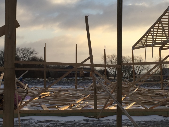
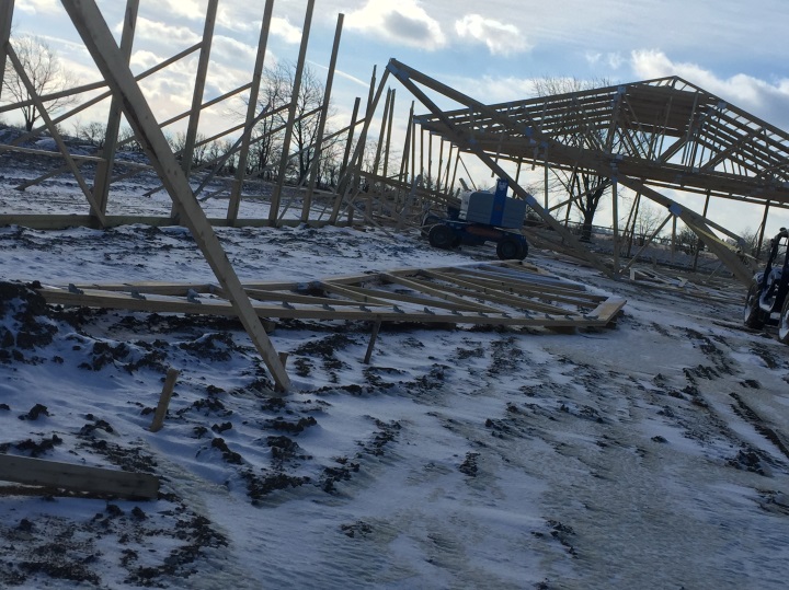
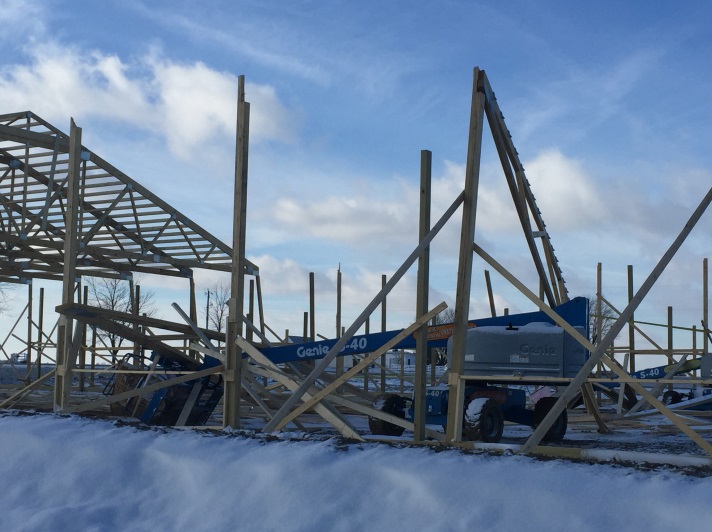
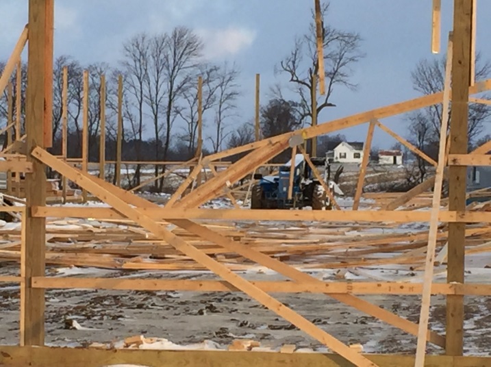
This particular building’s RDP had designed its roof system so as 36 feet of roof closest to each endwall was to be sheathed with 7/16” OSB on top of purlins. Had sheathing been installed, before moving forward, as well as following column, truss and roof plane (purlin) bracing guidelines – this wind induced failure would not have spoiled an otherwise happy Christmas morning.

Proper Screw Location for Post Frame Steel Cladding

Proper Screw Location for Post Frame Steel Cladding

It was a pleasant October evening back in 1985 in Blacksburg, Virginia. My friend Dr. Frank Woeste was then a College of Agricultural and Life Sciences professor at Virginia Tech (officially Virginia Polytechnic Institute and State University) and he had invited me to teach one of his classes for a day, in exchange for him providing some basic engineering software to design post frame building columns, roof purlins and wall girts.

Back in 1985, Virginia Tech had not yet become a NCAA football powerhouse it grew into under the direction of Hokies’ head coach Frank Beamer – having participated in post season bowl games for 23 consecutive seasons starting in 1993. This also long predated an April 16, 2007 tragedy when Virginia Tech student Seung-Hui Cho fatally shot 32 faculty members and students, wounding 17 others before killing himself on campus. This shooting remains as the third deadliest mass shooting committed by a lone gunman in United States history.

Mid-way through an evening with Frank, after digesting a hearty meal and debating whether hops in our consumed liquids were a fruit or a vegetable (they actually are neither – they are flower cones), we digressed into Dr. Woeste’s research’s true essence at Virginia Tech – post frame buildings and prefabricated metal connector plated wood trusses.

Narrowing things down, a lively discussion occurred (including some of his grad students) on whether steel roofing and siding for post frame buildings should be attached with screws through ‘flats’ or on high rib tops.
You may be wondering what brought this particular subject to mind after so many years? In case you happened to, my Facebook friend Trenton had asked me this very question recently.

For years steel roofing and siding had been attached with ring shanked nails (read more about this and Dr. Woeste here:

( https://www.hansenpolebuildings.com/2011/12/ring-shank-nails/). Traditionally nails were located upon high rib crowns – knowing not all nails would be identically driven through steel into underlying wood. The belief was that rain running off a roof would never get high enough to leak around improperly seated nails on high rib tops!

So, what would happen if screws were improperly placed in those steel high rib tops?

Properly designed post frame buildings are dependent upon diaphragm action provided by the steel skin (roofing and siding). Numerous tests have been done to confirm shear strength of panels as properly fastened. When screws are placed through high ribs, there is a 5/8 to ¾ inch gap between high rib underside and framing below. Screw shanks can flex within this space, reducing shear load carrying capacity of this sheathing system.

Furthermore, screw flexation in this gap, allows steel panels to move slightly under wind or seismic loads, eventually contributing to slots being formed in steel around screw shanks, and over time, causing leaks.

Ultimately Frank and I agreed with every steel roofing and siding roll former – screws in flats, not on ribs!