Post Frame Barndominium Exterior Wall Questions
Reader IAN in RIDGWAY writes:
“I am looking for help understanding a couple of exterior wall questions.
- My county is enforcing the 2018 IECC for energy efficiency. In my region this requires R-20 cavity + R-5 exterior wall assembly. From everything I’ve read, this means a continuous layer of 1″ rigid between the framing members and the metal siding. Is this an accurate understanding in your mind? Does the 1″ of rigid between framing and siding affect the integrity of the structure at all? Are the fasteners that are shipped with your kits long enough to accommodate the 1″?
- We will be living in our pole building, which means we will need to meet minimum code standards for receptacles at the exterior walls. I am under the impression that the poles must remain whole and are not designed to have a hole drilled through each for ease of pulling wire. Am I correct here? What is the suggested solution? Conduit everywhere below my slab?”
Mike the Pole Barn Guru responds:
 Nice to see jurisdictions enforcing IECC (International Energy Conservation Code) requirements, as it will result in more energy efficient structures. In Ouray County, you are in Climate Zone 6B. This requires ceiling R-49, wood frame walls of R-20 plus R-5 (or R-13 plus R-10) where second value is continuous insulation and slab edges to have R-10 four feet deep.
According to Martin Holladay (Green Building Advisor editor) your continuous insulation is just as effective when installed on the interior of your wall framing. This is very important when it comes to fully engineered post frame construction. Properly engineered, post frame construction relies upon shear strength of steel skin to transfer wind loads through building planes to ground (https://www.hansenpolebuildings.com/2011/12/lateral-wind-loads/). Having rigid insulation between framing and siding would reduce or negate your siding’s shear strength and result in a less than satisfactory outcome. My recommendation would be to use a Weather Resistant Barrier on the outside of the framing, directly inside of steel siding. Fill insulation cavity with unfaced batts (preferably stone wool such a Roxul as it is not affected by moisture https://www.hansenpolebuildings.com/2013/03/roxul-insulation/) or BIBs (https://www.hansenpolebuildings.com/2011/11/bibs/), then a well sealed rigid insulation board between framing and interior finish. Done this way, your wall will ‘dry’ to the exterior, making your home’s HVAC system less responsible for reducing interior humidity levels.
Your wire pulling is far easier than you may have initially envisioned.
Very little drilling, if any, will be needed for holes in order to run electrical wires. Wall framing (girts) extend or are placed so as to leave a 1-1/2 inch space between outside of wall columns and siding.
Think of a hole being drilled through as being an “open knot”. Lumber grading rules refer to these as being “Unsound or Loose Knots and Holes” due to any cause. Most structural framing – like wall girts and roof purlins or posts and timbers are graded as Number 2.
For practical purposes, a hole up to just less than ¼ of board face being drilled through will be within grade in #2 lumber. Example: 3-1/2” face of a 2×4 a hole up to 7/8” may be drilled through, as often as every two feet. Allowable hole sizes are reduced and spacing increased for higher grades of lumber.
Any holes drilled through pressure preservative treated lumber or columns, especially near grade, should be treated with a Copper Naphthenate solution. Copper Naphthenate is available as a brush-on (Cuprinol No. 10 Copper-Green® Wood Preserver https://www.homedepot.com/p/Copper-Green-1-gal-Wood-Preservative-176223/300502829)
or spray-on(https://www.homedepot.com/p/Copper-Green-Wood-Preservative-14-fl-oz-
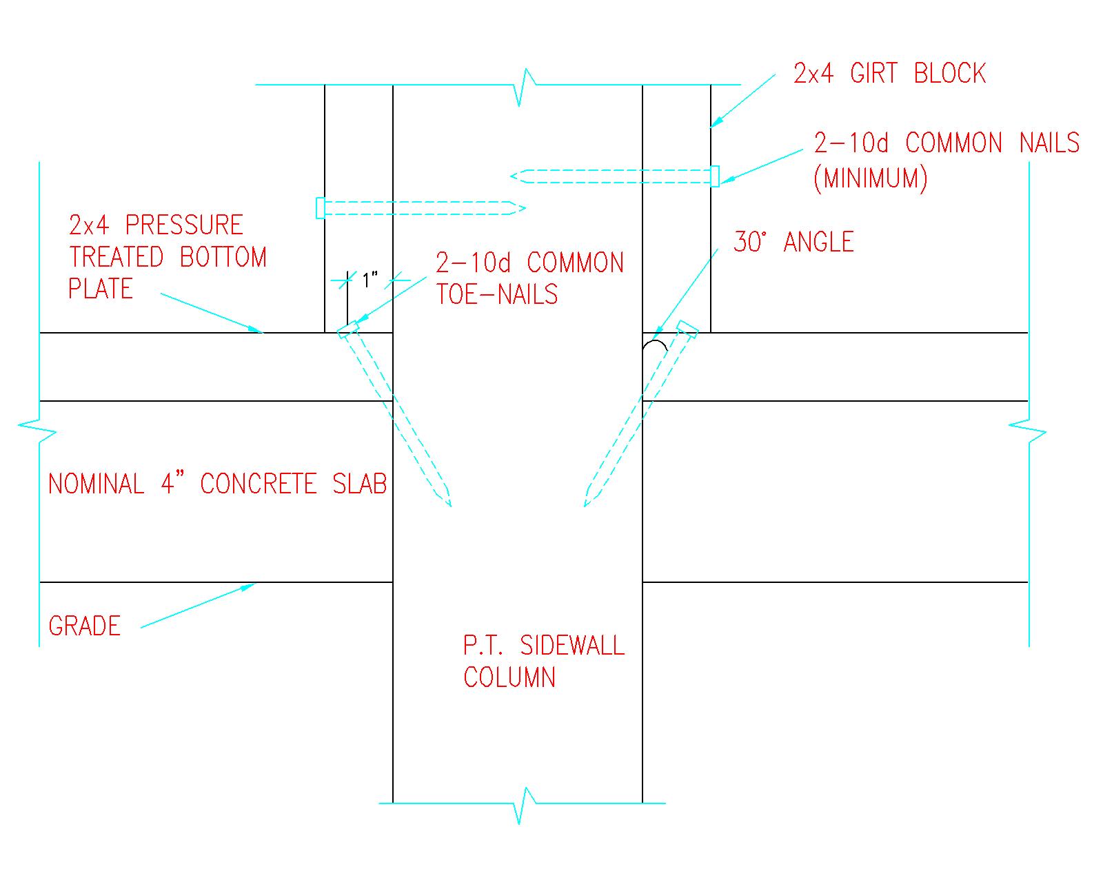
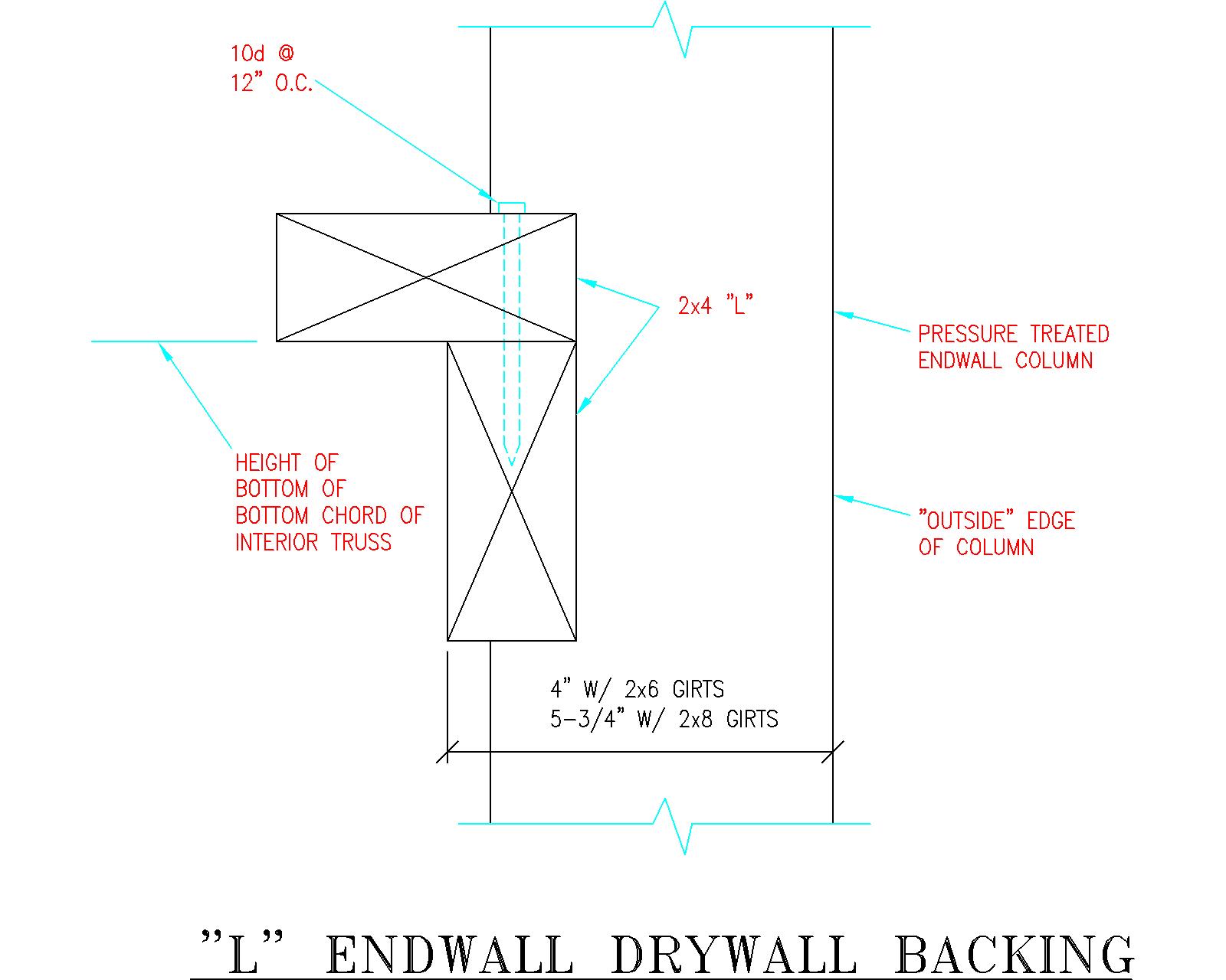
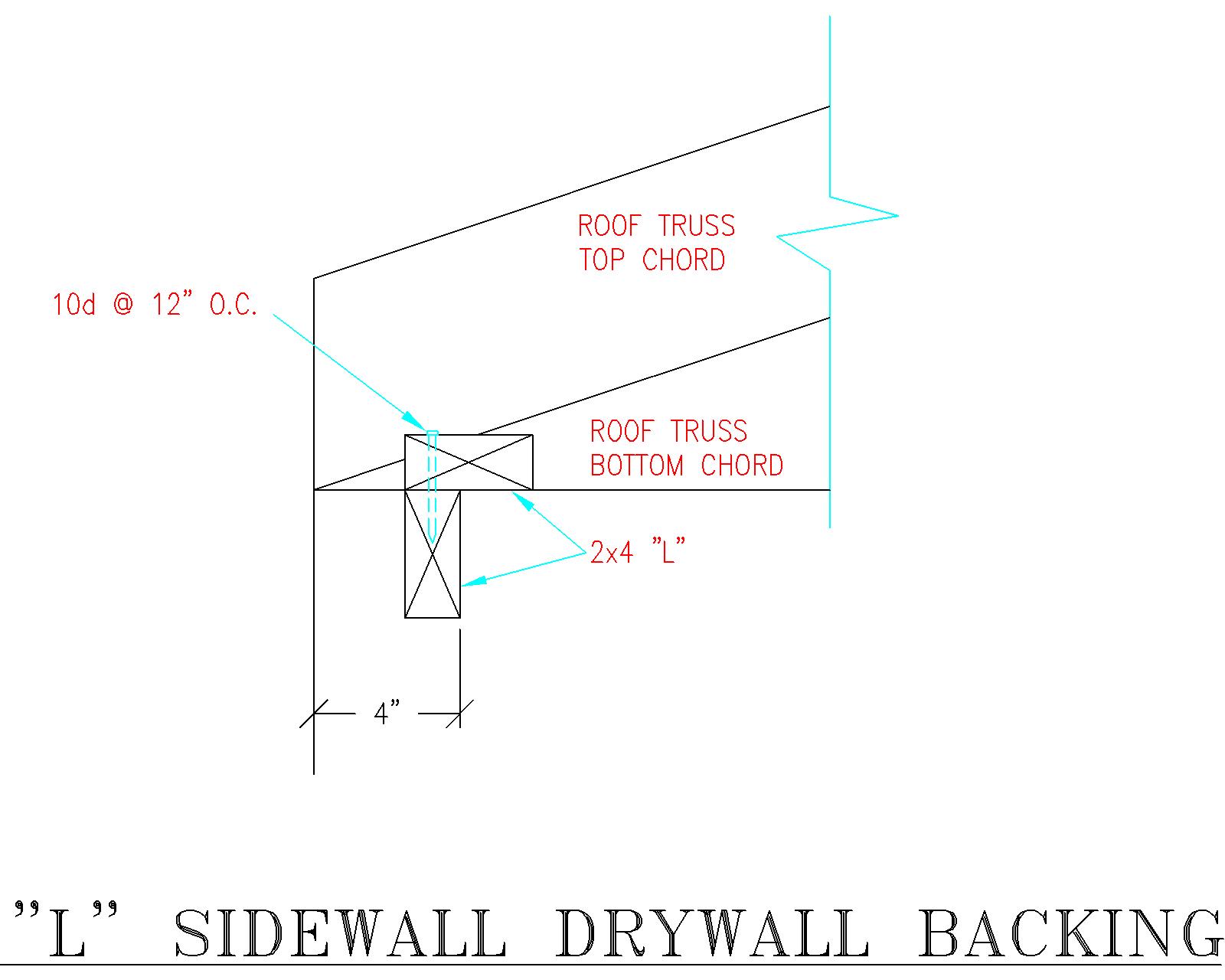 Figure 29-4: L Sidewall Drywall Backing