Tag Archives: Morton Buildings

Barndominium on Expansive Soils

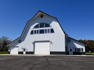
Post Frame Barndominium Building on Expansive Soils.

When I was a 1990’s post frame building contractor we trained our sales team to be diligent in looking at soil cuts near where our potential clients were considering erecting new post frame buildings. These cuts could tell us much about what was happening below the surface and potentially impacting digging conditions and ultimately performance of a new building.

Reader STACY in BERTHOUD writes:

“Hello.

My wife and I are looking at building a pretty large Barndominium on some lake front land that we have owned for more than 20 years but we are on expansive (high clay content) with a tested swell of 8-9%. 

Background Info:

The house portion would be approximately 2800 sq’ and the shop/garage portion is about 8000 square feet. The shop portion will store vehicles, Large RV, boats and leave recreational space for gym, Pickleball Court and an enclosed area for dusty work such as wood working and metal fabrication. 

We have a Morton out building there currently that is 42/75 with a fair amount of slab cracking. Although not hindered the function for a non heated barn, I would want the home to perform better. No Over Excavation was done but probably should have been. 

I cannot seem to find advice on if this is doable with a pole barn structure given the soils. They feel that deep cassions setting on a full perimeter grade beam is required which will totally blow the budget on a structure this size. I am trying to find out if this is true or is there a Over Excavation strategy that would be reasonable and how that perimeter detail might look for a tight, well insulated structure?

Any advice or specialist you could point me towards is greatly appreciated. 

Thank you!”

Mike the Pole Barn Guru responds:

My lovely bride and I live in an 8000 square foot, 44 foot tall post frame shop/house in NE South Dakota (we look across Lake Traverse at Minnesota). Minnesota is known as the land of 10,000 lakes. Many of these lakes resulted from glacial erosion causing physical and chemical changes creating small particles required to form clay soil. This clay sediment is both very fertile and makes for excellent lake bottoms!

Our particular building site had significant amounts of clay and we chose to excavate it out (over excavate) and replace with compactable fill. Our site is also built up, so any rain or snowmelt runs away from our home. After 15 years of service we have only minimal hairline cracks in our slab on grade – even though we have been through winters of seven feet of frost! Our building has no perimeter grade beams and our columns are embedded in concrete six feet below grade.

Most Building Departments in your area require engineered soils reports prior to construction. A qualified geotechnical engineer can determine a best course of action to avoid or limit adverse reactions from clay soils.

Here is some further reading: https://www.hansenpolebuildings.com/2019/06/post-frame-construction-on-clay-soils/

and https://www.hansenpolebuildings.com/2020/07/barndominium-on-expansive-soils/

Horizontal Deflection in Scissors Trusses

In yesterday’s article, I gave credit to a post frame industry pioneer, Mr. Henry Getz, of Morton Buildings, for being innovative in the introduction of scissor trusses to post frame construction.

Now I will tell you, gentle reader, of a scissor truss consideration which you have probably never considered – horizontal deflection.

When sealed truss drawings are prepared for scissors trusses, they will always state to allow for a certain distance of horizontal movement (deflection) from the truss. Why is this?

Scissor TrussConsider the look of a scissors truss, both the top and bottom chords are designed with a slope. As downward loads are placed upon the truss, it is going to tend to push the ends of the truss apart, as no straight line bottom chord exists to resist tension loads.

TPI (Truss Plate Institute www.tpinst.org) does limit the maximum horizontal deflection of scissor trusses to 1.25”. The concept is to design the scissor truss to wall (or post frame column) connection, so as to allow the ends of the trusses to slide back and forth. Simpson Strong Tie (https://www.hansenpolebuildings.com/2013/08/simpson/) even manufactures special brackets designed for attaching scissors trusses and allowing for horizontal deflection.

Using my Magic 8-Ball (originally used as a fortune-telling device in the 1940 Three Stooges short, you “Nazty Spy”) I can see there could be some trouble in the future…..

If the scissor trusses are allowed to move horizontally, and a rigid ceiling (such as gypsum wallboard) is installed on the ceiling, something bad is going to occur at the intersection of the ceiling with the walls.

Cracking.

This movement could also raise havoc with enclosed soffit materials, where the truss could conceivably move far enough so as to allow the soffit panels to start falling out.

When it comes to scissors trusses in post frame buildings, my thought is to firmly affix the ends of them to the sidewall columns. This will avoid both of the above challenges and the columns will easily absorb any deflection within their limits of bending.

Now there is one other thought….as the scissor trusses are deflecting horizontally, the overall height of the truss is changing as well. Considering a 40 foot span 4/12 roof slope, at maximum allowable horizontal deflection, the overall height at the center of the truss is going to deflect downward somewhere in the neighborhood of two inches!!

If your post frame building has all scissor trusses, then this sort of movement may not be detectible, however a building with one portion scissored and the other flat bottom chorded trusses, there is a possibility of it being visible to the naked eye!

Origins of Colored Steel

Where the Idea of Colored Steel Siding and Roofing Started

Back in the Stone Ages, when I first entered the post frame (pole building) industry, factory pre-painted steel siding was still in a relative infancy. So much so as most steel roofs were yet still bare galvanized! It was a rarity to have a colored steel roof!

Colors were relatively limited (red, white, blue, green, gold, beige and brown) and the paint was not the greatest. Read about polyester paint here: https://www.hansenpolebuildings.com/2014/05/polyester-paint/), but they were colors and the world was overjoyed!!

But where did the idea of painted steel come from?

As the late, great Paul Harvey would have said, now here is …. the rest of the story….

Henry Getz began his career working at his father’s company, Interlocking Fence Company of Morton, Illinois. Interlocking Fence Company started as a mail-order farm supply company providing fencing and other items needed by farm families. The company later offered a Quonset-style building with a laminated arched rib covered with galvanized sheeting. Seeing the potential in another style of building, Getz began moving the company into post-frame construction.

From the start, Henry constantly sought the “something extra” to offer customers, and in the early 1950s he introduced one of his most important innovations: the addition of color to otherwise plain galvanized sheet-metal buildings.

Though he was told farmers would never pay more for color, Henry pressed ahead. The first color introduced was stained red and incorporated into the gable trim. Soon after, the company added the option of using colored trims for sliding doors, beginning with red trim and track.

As post-frame construction gained popularity, the Quonset-style building was discontinued, and Henry and Interlocking Fence Company began constructing the post-frame structures familiar today.

Color-SwatchesBelieving color was spurring the industry’s growth and offered an opportunity to expand into the commercial building market, Henry sought out builders interested in transitioning to a painted steel panel. The assembly of a like-minded group was part of an effort to decrease the cost for all involved parties. Although this effort was ultimately unsuccessful, Henry persevered and began offering painted steel panels himself. His advertising at the time strikingly compared a building without color on the roof to a mannequin without hair!

Some astute readers may have made the connection between Henry Getz and Morton, IL. For those who didn’t – think “Morton Buildings” and you will have it!

When I consider the tens of thousands of building projects I have had the privilege of working on, I have to doff my hat to Henry Getz for the insight in starting what has become a beautiful palette of colors!

Roof Sliding Door

Yes – sliding doors can end up being placed on a roof…..just not on purpose!

The photo is of a sliding door on a Morton Building owned by a friend of a Hansen Pole Buildings employee. As this is an older building, it is not intended to be a negative commentary on any of the current buildings being constructed by Morton Buildings.

Considering the tremendous number of pole buildings Morton Buildings has constructed over the years, there are truly relatively few negative commentaries on the ‘net in regards to problems or issues faced by Morton Buildings’ owners.

roof sliding doorThere are some issues with this sliding door which I would like to point out, ones which could be from nearly any pole building provider – not just Morton Buildings.

Note what appears to be a 2×6 “top rail” or top girt of the sliding door. Sliding doors with wood members tend to be heavy, as well as the top rail is most probably under designed to be able to adequately carry the weight of the sliding door, without (at the least) some sagging occurring. This is not the reason for the failure of this door.

Properly designed, sliding doors should have a metal bottom girt (or bottom rail) which interlocks with a steel guide rail which is mounted to the pressure preservative treated skirt board (splash plank) in the direction the door slides. In most cases, this, in itself, should have prevented the door from flopping over onto the roof.

For the sliding door to have ended up where it is, the latches on the door (one at the jamb and the other to the other leaf of the door) must not have been properly latched by the building owner. There also should have been a steel guide mounted to either the concrete floor or to a stubbed column set in concrete between the sliding door leaves at the bottom. When properly closed, the sliding door leaves would be tight into this guide.

Besides the obvious (the sliding door now located on the roof), once the sliding door literally blew up, the building now became a partially enclosed building. The wind forces applied to the members of a partially enclosed building are much greater than those of a fully enclosed building. Think of the opening as now being the “throat” of a balloon and the building as being the balloon itself. These added, and undersigned for, forces, could easily have contributed to the failure of some or all of the building.

In this case, the Morton Building owner was actually lucky – all which needs to be done is to repair or replace the sliding door track, hardware and the door itself!

Nailing Steel Roofing on Pole Barns

When I was a “newbie” to the pole building industry, pretty much everyone was nailing steel roofing and siding using ring shank nails with a neoprene washer beneath the head. In theory it was all great and wonderful. In reality there were some issues:

No matter how expert the hammer swinger was, there is no way every nail could be driven into exactly the same snugness. Even if the ‘swingee’ could do everything identically from the business end, lumber is organic and varies in density from board-to-board (sometimes even in the same board). Hit a knot? Not good.

This results in some nails being over driven, others under driven. Both situations resulted in leakage. Leaks are bad – building owners somehow have no sense of humor about them.

Swing the hammer and have the head glance off the nail? Those hammer dents in the steel are just not very attractive.

Try to remodel a building where the steel has been nailed on? Good luck having any salvage.

The Hansen Pole Buildings shipping warehouse is an older pole building (built by someone else long ago) with nailed on steel. When we purchased it, the roof had so many leaks it might as well have been a colander!

Consider how a nail enters the wood. It forces the wood fibers down. Watch a screw being driven in – it pulls the wood fibers up. Wood has an inherent “memory” and as those disturbed fibers return to their natural state, they want to push nails out (resulting in leaks) or pull screws in (creating even a tighter seal). We saw evidence of this in the warehouse we purchased, with about 10% of the nails sticking up out of the steel by anywhere from ¼” to a full inch above!

Early in the 1980’s most builders and suppliers moved from nails to screws, which are a superior fastener.

When I owned M & W Building Supply, we switched over to screws in about 1982. When our clients needed erection labor, it was provided by Farmland Structures (owned by Jim Betonte). Jim was astounded when a couple of his crews told him they were driving the screws in…..with hammers!

The only way for Jim to convert them, was he bought each of his crews a screw gun. Once they had used the guns, they were sold on the idea of screws.

Ring Shank Nail with WasherWhat got me set off on this rant was a quote which was forwarded to our office, by a client, from Ameribuilt Buildings, a pole builder based in Waite Park, MN. Under “Ameribuilt Buildings Standard Features” is “Nailed steel roof (galvanized ring shank w/silicone washers) NOT SCREWS!!”

Somehow Ameribuilt must be very proud of using technology from the 1970’s as the actually put “NOT SCREWS” in bold type!

It rather reminds me of the information on the Cleary Buildings website (https://www.clearybuilding.com/feature_PDFs/NAIL_vs_SCREW.pdf) where Cleary says: “We will continue to follow the philosophy that a nailed roof is the best application. The nail is on the rib of the steel and the rib will shed water away from the nail. “

Wonderful in theory Cleary, wish your staff could have been around when we used two cases of ‘super whammy million year’ caulking to seal up all of the leaks from around the nails holding down our steel roof!

Even Morton Buildings has some of the nailing Kool-Aid left around. Now Morton does use nails manufactured by Maze nails (Maze produces a quality part domestically), however a nail is still a nail, even on a Morton Building.

Realistically why would anyone seriously consider nailing steel roofing? I can think of only two reasons – they are far less expensive than screws, and there is a perception the installation process is faster (which means money in the pockets for builders).

Besides the obvious issues with nails mentioned above, there are some strength issues involving diaphragms, when using nails.

In the National Frame Builders Association Post-Frame Building Design Manual in Table 6.1 is “Steel-Clad Roof Diaphragm Assembly Test Data”. Test Assembly Number 4 is the only one which utilized steel fastened with nails, including the nailing of panel-to-panel. The ultimate strength of this assembly was 1930 pounds per foot. Test Assembly Number 13, of the same table” was “our test”. We used thinner steel than the nailed test (30 gauge instead of 29), spaced the roof purlins further apart (28 inches on center instead of 24 inches) and placed rafters at twice the spacing (12 feet instead of six feet). We also used screw fasteners in the flats, instead of nails on the high ribs.

The results might surprise the casual reader – we achieved an ultimate strength of 9600 pounds per foot, or nearly 500% stronger than the test results from nailed steel.

If the leaks don’t prove which is better, the numbers do!

Still convinced nailing steel roofing is “easier”, or some company tries to tell you it’s “better” without any proof? Be sure to order several cases of “lifetime” caulk for the nailheads…because you will eventually need it.