Tag Archives: building officials

Insulation Addition, A Clear Span Monitor, and Post Frame Code

This week the Pole Barn Guru discusses adding insulation to an existing building, building a monitor style building with a large clear span main level, and a building official misinforming a potential client.

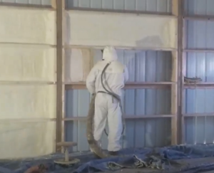
DEAR POLE BARN GURU: I currently have a 30×50 Wick building on some property which I purchased last May. The building is 15 years old. It had a white faced batt insulation rolled out over the roof and wall purlins. The building is heated with a 80000 btu forced air furnace and has a 3.5 ton 16 seer AC unit as well. The building is used as a mancave/shop for piddling on projects. The design has an open ceiling. I would like to add additional insulation at the roof deck level. I have a local insulation contractor who has good reviews come and look at it. He is suggesting adding a 4″ thick x 24″ wide WMP50 batt insulation between the roof purlins. The research I have done suggests to not lay a batt over a batt as you could create an area where moisture cannot pass through. If the new vapor barrier of the WMP50 is sealed correctly would there still be an issue? I’d like to keep the open ceiling design as I currently have a car lift between two of the rafters and need to be above raise the vehicle cab above the bottom of the lower rafter horizontal. This kills the idea of putting in an insulated ceiling thus creating an attic space. Any thoughts on what the contractor wants to do as well as other ideas how to better insulate the roof?

Thanks… DAVE in MARSHALL

DEAR DAVE: You want to avoid having two vapor barriers. Easiest solution would be to poke holes in your existing white facing often enough to not create any two vapor barrier zones, then add your new product, making certain all joints between rolls are sealed.


DEAR POLE BARN GURU: Is it possible to have a monitor style barn to use the open upper level as a living quarters and not need support legs under to keep the lower shop level open. JOE in PUEBLO

DEAR JOE: It can certainly be done, and there are a few ways to get there.

second floor
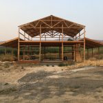
Here is how we did it for my Sales Manager, Dan, in my past life when I was a post frame building contractor. Dan wanted a 30′ x 50′ monitor style building for a garage/shop and then an office above. We had engineered a clearspan roof/floor truss combination for support of wings and second floor. This system had a double truss every 10 feet. At eight feet from each outside wall, we mounted columns to these trusses to support roof of raised center. Joists we placed for ceilings and floor system. With an 8/12 roof slope, upper level used scissor trusses with a 5/12 interior pitch.

For monitor buildings without as much front to back depth, we can design with parallel chord flat trusses used as girders and bury them in knee walls of raised center portion. This often precludes ability to have windows along upper level sides.

With post frame construction, if you can dream it, chances are good we can design it.

DEAR POLE BARN GURU: Hello, I am looking at building in Chippewa County, Wisconsin. I absolutely love the idea of doing a Pole Barn House/Attached Garage. The problem is that I cannot get an answer if I can build one in the county. The building inspector has been continually telling me that they cannot be built if the garage is directly attached.

I have attached a pdf of the floor plan for said building
Can you help with this? JEFF in STANLEY

DEAR JEFF: While your pdf did not make it, there is no reason you should not be able to have an attached garage, just as you could with any other structural building system. Building Codes certainly allow for attached garages (drive through any subdivision in our country), with appropriate fire separation between it and living spaces.

If your inspector persists, please ask him or her for a written copy of whatever ordinance this advice is based upon. Chances are good there is not one, and it is based upon some personal opinion. Should documentation actually be produced, please forward to me so I can go do battle for you.


Guest Blog Specifics

Guest Blog Specifics.

This column has been recognized multiple times as a top construction industry blog – second World Wide in 2017 and 2018! It also has a significant readership, with articles having been read as many as 240,000 times. Due to this popularity, I receive numerous requests to guest blog.

Who should consider submitting a guest blog?

Industry Suppliers – have a new product you want to make my readers aware of? Or maybe just to reinforce your current products’ benefits.

Competitors – why not? I hope you have learned a fraction from me as I have from you. Use this as an opportunity to educate me and my readership.

Contractors – want to share some of your experience? Have a great idea? Or maybe you know a faster, better way to assemble some portion of a post frame building. This blog presents an ideal forum to do so.

Clients – share your story. Using your building for a unique or interesting purpose? We’d like to have others read about it. Or, interesting tidbits during construction of your post frame building.

Registered Design Professionals – architects and engineers, keep it conversational. Talking above reader’s level, without thorough explanations, isn’t what we or readers are looking for.

Building Officials – I am certain many of you have some interesting stories to tell about post frame buildings.

Anyone else who feels an interest or love for post frame construction and wishes to share will be welcomed.
There are some rules when it comes to submitting an article for consideration:

Length – it should be 300 words or more in length. If over 800 words, please break it up into approximately equal segments of no more than 800 words and it can be run consecutive days.

Content – has to be specific to post frame (pole building) construction. Must be informative or entertaining (both being preferred). Tell a story, make it interesting. No profanity, we have a PG audience. Also, nothing political or religious should be used. Article can speak to benefits of a product or service however it cannot be a blatant advertisement for you or your product. Article cannot include links to competing or non-relevant businesses (no adult content). You may have one ‘do follow’ link to your site in your article (again – no adult content). There will be no cost to publish, however if you have a do follow link in your submission, we request you choose one of our existing articles and place it on your website with a do follow link to Hansen Pole Buildings.

Relevant photos or video tied to your content makes for even better articles and increases entertainment value.

Unless you specify otherwise, we will give you credit in article for your submission. A brief (line or two) bio will be appreciated.

Not all submissions get used. Articles are often posted several weeks, or months, in advance. Please be patient. We reserve rights to edit your content when deemed appropriate.

Please send all submissions in Microsoft Word to: PoleBarnGuru@HansenPoleBuildings.com.

Building Code & Pole Buildings

When Plans Examiners Try to Apply the “CODE” to Pole Buildings

Today’s example happens to come from the State of Michigan, however it could happen in any Building Permit issuing jurisdiction in the U.S.

What is most interesting to me about this particular example is, last November I was invited to be a presenter at a meeting of Building Officials representing pretty much the northern half of the non-UP (Upper Peninsula) portion of Michigan. The topic was how the Building Codes apply to post frame (pole building) construction, and it was determined as a resultant, the Building Code could not be applied directly.

Building DepartmentLet’s have some fun with plan reviews, shall we?

(plan reviewer comments in yellow, referenced Code in italics below)

Footing size indicated is too small, (minimum 28″ round x 12″ thick) for sidewalls, or provide load calculations for each column. R403.1 to MBC 1805.7

R403.1 General. 

All exterior walls shall be supported on continuous solid or fully grouted masonry or concrete footings, wood foundations, or other approved structural systems which shall be of sufficient design to accommodate all loads according to Section R301 and to transmit the resulting loads to the soil within the limitations as determined from the character of the soil. Footings shall be supported on undisturbed natural soils or engineered fill.

Following this section of the Code is a Table which gives footing requirements for conventional light-frame construction, 4-inch brick veneer over light frame or 8-inch hollow concrete masonry, or 8-inch solid or fully grouted masonry.

The Code reference does not address footings for isolated, widely spaced columns.

Carrier beam size indicated is too small, three – 2” x 12” carriers minimum, required to carry truss and roof load. Table R502.5 (1)

The Table referenced is for exterior bearing walls in stick frame construction, where the dead load weights of shingles, roof sheathing, and gypsum drywall must be accounted for. It also is based entirely upon ground snow loads, without factoring in the allowable adjustments for this particular building being heated, as well as having a slippery steel roof.

Footnote for most of my readers who are in parts of the country where trusses are attached directly to the columns – this particular pole building is designed with a single truss every four feet, sidewall columns every eight feet and a header (aka “carrier beam”) attached to the columns to support the trusses.

The Table is also based upon a uniform load, which would be applicable for instances where trusses were placed every two feet (ala stick frame construction). Instead the carrier beam, is supporting a concentrated load at the center and every other truss rests directly on top of a column. This effectively reduces the load being carried by the beam by 1/3!

Confused?

Think of the load applied from a truss at two foot centers as being X. In an eight foot area, there would be an X at two, four and six feet or 3X. A truss at four foot only would carry twice as much load as a truss at two feet, or 2X. 2X divided by 3X = 2/3.

Carrier beam nail fasteners are sized too small and additional fasteners are required. Alternate structural screws, lags or bolts may be used. Submit revised fastener design. R 602.2

In my humble opinion, the Plans Examiner meant to reference R 602.3 which lists fastener schedules in Tables. The Tables do not even begin to address the connections found between a “carrier beam” and a column. The Plans Examiner appears to have possibly neglected to note the design presented has the carriers notched into the faces of the bearing columns, resulting in only enough fasteners being required to resist the uplift loads.

Buildings with an eave height 10′ or greater will require knee bracing or a full length diagonal brace in each corner. R301.1.1 to MBC1609.0, 2303.2

R301.1 Design. 

Buildings and structures, and all parts thereof, shall be constructed to safely support all loads, including dead loads, live loads, roof loads, flood loads, snow loads, wind loads and seismic loads as prescribed by this code. The construction of buildings and structures shall result in a system that provides a complete load path capable of transferring all loads from their point of origin through the load-resisting elements to the foundation.

It appears the reviewer’s comments are some sort of a local interpretation of how to handle the requirements of R301.1

I do believe I have previously presented an overwhelming case as to why not to use knee braces: https://www.hansenpolebuildings.com/blog/2012/01/post-frame-construction-knee-braces/

But what about a diagonal brace?

The entire concept of a diagonal brace in a wall is to assume the siding (in this case steel panels), lacks the ability to carry the shear loads being applied to the building.

Having been personally involved in the testing of light gauge steel panels, I can attest to their ability to carry a significant amount of load. (Read more at: https://www.hansenpolebuildings.com/blog/2012/08/this-is-a-test-steel-strength/)

Going back to the assumption of the siding not being able to carry the load, the building being reviewed has 1841.8 pounds of shear force being transferred to each endwall. Keeping things simple, let’s look at what it takes to even attach the suggested braces.

Generously assuming each brace would carry ½ of the applied load, each end of each brace must be able to have a connection adequate to carry around 921 pounds of force. A three inch long 10d common nail (3” x 0.148” diameter) driven through a 1-1/2 inch thick member into another member (assuming the weakest commonly used framing species) will support roughly 128 pounds. It is going to take a lot of nails in a very small area to make the connection work.

To have made this entire process quick, easy and simple for all involved, and to keep the Building Permit issuing authority out of the potential liability problems for being possibly construed as becoming the engineer of record, would be to simply require all pole building plans to be submitted with the seal of a registered design professional (engineer or architect) as well as the supporting calculations.

Which is exactly what this particular client opted to do. Case closed.

Building Engineer: One Who Should Know Better

Over the years we have provided, to clients, several post frame buildings in a county in California which will remain unnamed in this blog.

This particular county has an actual registered building engineer who does the structural plan reviews.  Sometimes this can be a good thing, sometimes a challenge.

One of our clients recently submitted a plan (produced by one of our engineers and including all of the calculations) for a new barn. This particular building had a wood floor, supported by floor joists. The floor joists were attached to gambrel (old barn profile) roof trusses at each end, by joist hangers. The sidewall columns (and trusses) were spaced at 12 foot on center. The greatest distance spanned by the 2×10 #2 floor joists is 11’8”.

The building engineer who did the review came up with:

“Please take another look at the 2×10 floor joists. Using a live load of 40 psf, which may not be

applicable if the area is used for storage, #2 DF fail in bending. #2 Hem-fir is even worse.”

Now the lovely thing about the International Building Codes is the span tables listed in Chapter 23 for things like – floor joists!

It really does not take rocket science for the average lay person to look at Table 2308.8(2), “Floor joist spans for common lumber species”. The table lists Douglas Fir-Larch, Hem-Fir, Southern Pine and Spruce-Pine-Fir. Going down the 2×10 column, to the 24 inch joist spacing area, lets the reader know the least span for any of these species, in #2 grade, is 12-5.

NDS BookIn the event the building engineer did not choose to open the code book, there are free online resources which can be accessed. The American Wood Council has a very handy one at www.awc.org, which I use frequently.

My real peeve here – this plan check has now created unnecessary work for our engineer, and creates skepticism in the client’s mind.

Oh, by the way, our engineer had provided the calculations which prove the floor joists specified do work, the reviewing engineer neglected to look through them!