Installation Guidance on Truss-to-Post Connections
Originally Published by Frame Building News May 24. 2022
This article series has been focused on installation best practices as it pertains to long-span metal-plate connected wood trusses in post-frame buildings. We’ve explored the reasoning behind why truss handling on the jobsite should be minimized, and how proper jobsite storage and use of the correct hoisting equipment can be effective in achieving that goal. We’ve also explored how long-span trusses need to be adequately braced to the ground during installation, then properly restrained and braced to each other before sheathing is applied. Most recently, we looked at effective ways to apply permanent bracing to a truss system to ensure it performs as expected over the life of the building.
All of those elements are extremely important to mitigate the chance of something going wrong during truss installation and you end up at best having to hold up the project to make a repair, or at worst cleaning up a large and expensive pile of spaghetti. Yet, following all those best practices are for naught if the connection of the truss to the post or column is not made correctly. Unlike truss bracing, there are several ways to do this properly, and different regions of the country approach columns and truss connections differently. Instead of going into depth on the myriad of options, this article will talk about the big-picture issues that must be addressed.
Forces to Be Reckoned With
David Bonhoff, Ph.D., P.E., is a professor emeritus at the University of Wisconsin-Madison. He has written several technical articles providing thorough analysis of various aspects of post-frame buildings, including truss-to-post connections. In a recent discussion on connection best practices his primary focus was on providing resistance to all of the forces that are applied to these connections. “Engineers typically address these forces as a shear force that acts perpendicular to the column, and an axial force that acts parallel to the column,” says David. “Then there are bending moment forces where the members within the connection want to rotate.”
Of those three forces, the bending moment is generally the biggest concern for the building designer and often dictates the size of truss and column members. That said, all of these forces influence the amount and direction of load being resisted by a truss-to-post connection, yet the connection has to successfully resist them all.
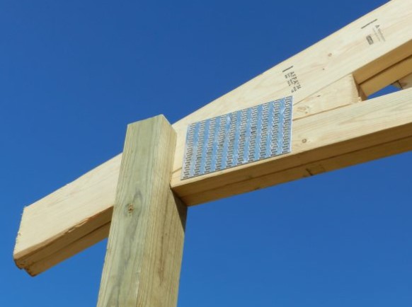
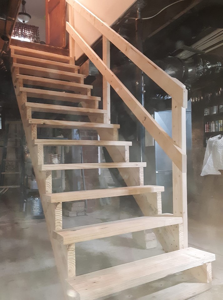
An example of a truss-to-post connection with a solid-sawn column (Hansen Pole Buildings, LLC photo)
Steve Kennedy, P.E., an engineer for Lumber Specialties who has been designing long-span trusses for post-frame buildings for many decades, says, “When enough load acts on a truss, whether it’s a snow or wind load, and the truss wants to move, that truss-to-post connection needs to be stiff enough to resist it.” If it doesn’t provide sufficient resistance the truss will move and the end result will be failure at that connection.
A Pantheon of Columns
Post-frame columns are typically either solid-sawn or laminated. A laminated post is any column assembly that consists of two or more layers of dimensional lumber joined together by either glue, nails, a combination of nails, screws and/or bolts. Glue-laminated columns are typically horizontally laminated, while mechanically laminated columns are most often vertically laminated.
Some laminated column assemblies are unspliced, meaning each layer is comprised of a single piece of dimensional lumber. For several reasons, it has become more common for laminated assemblies to come spliced, where at least one of the layers is comprised of multiple pieces of dimensional lumber.
While all of these approaches are acceptable, NFBA’s Post-Frame Construction Guide points out that spliced, mechanically laminated columns offer a significant advantage when it comes to enabling “saddled” truss-to-post connections (page 5):
“These columns can provide efficient truss connection details because the length of the different laminations can be varied, creating a slot of the truss to slide into.”
On the Level
The first step in ensuring a good truss-to-post connection is making sure the bottom chord of the truss rests completely on the top of the column. “You want the bending moment (rotation) forces in that connection transferred to every ply in the post,” says David. This is done through the fasteners to the outer plies and through physical connection to the inner plies.
David also stresses that if the truss (or trusses, if the column is supporting multiple plies) is sandwiched between plies of the laminated column, the truss should be in full contact with the outer plies. “When they’re snug, that will produce considerable friction between the truss and post members, adding stiffness to the connection.”
Consistent column height and every truss-to-post connection is also important. “Whether the column is solid-sawn or laminated, it’s critical all the posts provide a consistent height to ensure the truss bottom chords are level once they’re installed on top of the columns,” says David.
He points out it can be difficult (though not impossible) to resolve a situation where the inner ply of the column is too high. “In that scenario, it’s beneficial to have one of the outer column plies spliced. You can then mechanically laminate it in the field once you’ve cut down the inner ply to the height you need,” says David. “Another approach is to purposely leave the inner ply short and you can insert shims in the field to get that full connection in the inner ply.”
On occasion, it may make sense to shim the column at the foundation. “If you are setting columns on a slab and your slab isn’t perfectly level, you can shim the bottom of the post with one or more thin layers of polyethylene,” says David. “It’s a great material because it adds a moisture barrier to the bottom of the post where it comes into contact with the concrete, and the plastic has stronger resistance to crushing than the wood.”
A “Fasten-ating” Approach
“The key to the truss-to-post connection is making sure multiple fasteners are sufficiently spaced apart so they don’t share the same wood grain and aren’t too close to the end of a member that they cause it to split,” says David.
Truss-to-post connections can be accomplished with nails, screws, and/or bolts. David says, “The availability of proprietary fasteners has really increased over the last decade, so post-frame builders have a lot of options today. You just have to be careful that whatever fastener you are using you understand how many you need and how far apart they need to be spaced.”
“Ideally, you want a 12-16 inch truss heel at the connection so you have sufficient area to space out your fasteners,” says Steve. “Again, the whole goal of the connection is to resist the rotation of the truss members as the truss is resisting loads like gravity, wind, snow, etc.”
From his experience, David prefers bolts. “Bolts have the advantage of going all the way through the truss-to-post connection, so they provide increased resistance to shear and also suck the plies together to create greater friction. The larger diameter of the bolts also increases their resistance to corrosion. In addition, with bolts you need a lower total number of fasteners for the connection, so you can space them farther apart, providing greater bending moment resistance.”
The Bottom Line
Proper long-span truss installation in a post-frame building presents several challenging elements. While minimizing lateral bending during handling and adequately bracing trusses during installation are very important to ensure trusses aren’t damaged, compromising their ability to perform over the life of the building, proper truss-to-post connections are the most vital aspect of truss installation. While there are many options when it comes to column configurations and fasteners, the key is ensuring the truss bottom chords are level, are in full contact with the column material, and are fastened using an approach that maximizes the stiffness of the connection to resist truss member rotation.