Dear Pole Barn Guru is normally my Monday Feature, but lately I’ve gotten backed up on questions – so in honor of Friday the 13th, am hosting an additional segment. This is why I encourage those with questions to provide email addresses, which are used for nothing other than answering your questions. We don’t SPAM or email you anything other than what you ask for.
If you want a quick answer, please be sure to answer with a “reply-able” email address.
Email all questions to: PoleBarnGuru@HansenPoleBuildings.com
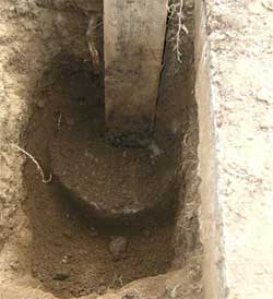
DEAR POLE BARN GURU: We are in a no frost area with no snow load, so why are the post piers so large and deep?? NOT DIGGIN IT IN CA
DEAR NOT DIGGIN’ The column embedment (depth and diameter of the holes) has to do several things, including:
Resisting uplift – the columns, their encasement (the concrete attached to the base of the column) and the “cone” of soil above the concrete bottom collar, must have sufficient mass to keep the building from being literally “sucked” out of the ground. (Think of the force applied to an umbrella on a windy day.)
Resisting overturning – prior to the engineering studies done over the past few decades, the “rule of thumb” was 1/3 of the column should be below grade. Modern technology has allowed this design to be far more scientific, as well as generally reducing the depth of the columns.
Keep the building from settling – while you state your building has no snow load, the information on your order has your building designed for a ground snow load (Pg) of 35 pounds per square foot. The footings must be able to support the dead weight of the structure PLUS any live loads which would be applied to it. These live loads include the weight of any snow, or potential snow. Your building also is designed for a light storage load attic space. Any roof truss design with this type of load, must be designed to support a 10 psf (pounds per square foot) dead load across the entire truss bottom chord (12,960 total pounds on your 36′ x 36′ building) by Code. The storage area adds another 20 psf for another 8640 pounds. All of these weights have to be distributed by the concrete encasement, to the soils beneath the building, with minimal settlement.
Your building has been designed with a 2000 psf soil bearing capacity, which is higher than what is allowed by most California jurisdictions. The use of this number, has actually allowed for the concrete diameters of most of the holes to be far smaller than if a lower number had to be used.
DEAR POLE BARN GURU: Should the sheet metal (steel) siding and roofing of a post frame building be grounded?
If so should it be bonded to the ground bar or ground rod of the building’s electrical panel?
My pole building sheet metal does not contact the earth. The metal is painted and may have electrical bonding between the panels either at a common fastener or bare spots in the finish.(or maybe not, who knows)
Also the electrical panel is installed on wood framing with no fasteners touching the metal siding. The electrical panel ground bar is bonded to ground rods but the bond is insulated from the metal siding.
I have looked at similar buildings(wood frame) in my area and see no evidence of grounding of the sheet metal except by accidental contact.
This building is used as a machine shop/storage building, no farm animals.
Is there a right way? or a better way? or does it make any difference? ZAPPED
DEAR ZAPPED: Should it be grounded? Maybe. Is it required to be grounded? No. As I admit to being “electrically challenged”, my best recommendation would be to contact your local licensed electrician. Here is the “skinny” from the NEC (National Electrical Code):
Structural metal. If exposed structural metal that forms a metal building frame is likely to become energized, you must bond it to one of these [250.104(C)]:
- Service equipment enclosure
- Grounded neutral service conductor
- Grounding electrode conductor, if sized per Table 250.66
- One or more of the electrodes of the grounding electrode system
This rule doesn’t require you to bond sheet metal framing members (studs) or the metal skin of a wood frame building , but doing so is a good practice. Size the bonding jumper for the structural metal per Table 250.66, based on the feeder or service conductors that supply the building (or structure). This bonding jumper must be:
- Copper where within 18 inches of earth [250.64(A)].
- Securely fastened and adequately protected, if exposed to physical damage [250.64(B)].
- Installed without a splice or joint, unless spliced by irreversible compression connectors listed for the purpose or by the exothermic welding process [250.64(C)].
DEAR POLE BARN GURU: How to install an equipotential ground in the concrete? Also is it necessary to ground the metal siding and if so best method. CONCERNED IN CALIFORNIA
DEAR CONCERNED: As far as “how” to install an equipotential ground or to ground the metal siding would be questions best answered by your electrician. My concern would be, do you even need to be concerned with this.
From the 2010 CEC (California Electrical Code) Article 547 (the red text highlight is mine):
Equipotential Plane – “An area where wire mesh or other conductive elements are embedded in or placed under concrete, bonded to all metal structures and fixed nonelectrical equipment that may become energized, and connected to the electrical grounding system to prevent a difference in voltage from developing within the plane.”
A post frame building is not an “all metal structure”, so the need for a equipotential plane, would not be existent.
The Code also does not require metal siding to be grounded.