An Excel Formula for Calculating Wall Girts, Post Size and Hole Depth
John Minor and I have been friends for nearly 30 years – since his then father-in-law (and my business partner at the time) convinced me John could sell post frame buildings. Well Rod was correct, John could sell buildings – not only for me (twice), but also for some of the better known names in the post frame industry – Morton, Stockade, Cleary and FBi just to name a few.
John is also a cutting edge innovator and has gone from selling post frame buildings, to manufacturing and providing components to the post frame industry. Current he owns and operates Central Perma-column (https://www.heartlandpermacolumn.com/). John is smarter than the average bear and he has the thirst for knowledge which few non-RDPs (Registered Design Professionals – architects or engineers) in the post frame industry do.
December 13, I received this text message on my phone: “I need your help with something”. Although I did not recognize the number it came from, it turned out to be John.
The conversation went on like this – John, “No worries. I’m trying to find an Excel formula for calculating wall girts, post size and hole depth.”
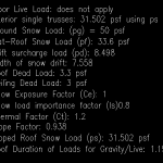 Me, “You would have to write one and they will be very complex due to the tremendous number of variables involved. I’ve thought about having a Wall Girt calculator on our website for Building Officials to use and the reality is, it is a huge undertaking. For it alone, requires all of the building dimensions including roof slope, is building enclosed or partially enclosed? Which means one has to know if doors are wind rated, and where they are placed. Also makes a difference as to where girts are located on building as wind forces are greater at corners. If girts are barn style on outside of columns, do they span a single bay or multiple bays? Then one has to account for lumber species differences as well as visual vs. machine grading.
Best bet would be to layout all of the parameters and put it out for bid on Upwork. Should specify which versions of Code and NDS you want to cover as well as it must conform to the NFBA design manual. For columns, you are now talking 25-35 pages of calcs.
Fun, eh?”
John, “Damn!”
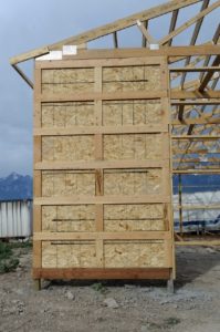
Those “simple” pole barns one drives by every day are in reality highly complex engineered structures (when properly designed). A full set of calculations for a small two car garage can generate nearly 200 pages of single spaced calculations to prove the adequacy of all structural members and connections, from the footings to the last fastener.
Don’t leave your new post frame building to chance – insist upon having only a building which has been designed specifically for you by a Registered Design Professional, on your site, with your dimensions and your doors!
 affected. Each wall must be supported perpendicularly, either with walls under or perpendicular to them, to ensure stability under forces from all sides. The shear force is transferred over the wall adjoining it, but no further. Uplift forces lift one end of a wall and push the other end down. This can result in a building toppling over. Uplift forces tend to be greater on tall narrow walls and lesser on longer walls.


