Client calls into our office at the end of the day Friday and talks with Sheila. He tells her his Building Official will only accept his new pole building construction with holes 48 inches deep, with a six inch thick concrete cookie in the bottom of the hole, and no concrete backfill around the columns.
Here is some background….
The building is a commercial pole building 34’ x 60’ x 13’ in Iowa. Because it is a commercial building, the client purchased engineered plans for the building, which includes all of the supporting calculations for the design.
While a hole for a pole building post might seem to be just a hole in the ground, lots of things are happening below the ground. The embedment has to be deep enough to put the bottom of the footing below the frost line. The footing beneath the column has to be large enough in diameter to keep the building from settling. The design must also provide for the resistance for uplift.
In this particular building, the downward load on the footing is just over 5400 pounds. The uplift force is 1120 pounds.
Now it is 4:50 on Friday afternoon, so I ask for the phone number for the Building Department, client instead, has me call him…..now the Paul Harvey appears….
The issue turned out to have absolutely nothing to do with any Building Official, and everything to do with the client’s builder (I know, a shock).
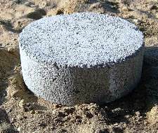
 The builder insists upon digging the holes with the 12-inch diameter auger he has mounted on the back of his farm tractor. He refuses to set the posts in concrete, because if he doesn’t get a post in the right place, he wants to be able to move it around in the hole. His idea is to dig a four foot deep hole, and drop a 12-inch diameter concrete cookie in the bottom of the hole!
I can foresee a myriad of potential problems coming up, even without breaking out my Ouija board, or shaking the Magic 8 Ball.
Problem Numero Uno – if these holes are approved by the field inspector, someone is either blind, or an envelope got passed. If the Building Department accepts anything which is contrary to the engineer sealed and approved plans, they have opened themselves up for an entire world of liability.
Assuming somehow they are able to pass the hole inspection – a 12 inch diameter concrete cookie covers roughly 0.76 square feet of surface. Applying a load of 5400 pounds to it, means the soil bearing capacity would need to be somewhere in the neighborhood of 7000 pounds per square foot (psf). Table 1804.2 of the International Building Code gives a value of 4000 psf for sedimentary and foliated rock and 12,000 psf for crystalline bedrock. Neither of these types of soil would be touched by the 12-inch farm tractor auger. The probability of settling issues on one or more of these columns – right darn close to 100%.
The diagonal distance across a 6×6 (actual dimensions 5-1/2” x 5-1/2”) is nearly eight inches. Those 12-inch diameter holes better be pretty much spot on and perfectly plumb, or there are going to be some very interesting looking walls (as in not very straight at the ground line).
Builder does not want to backfill any of the holes with concrete (builder says it will also rot the posts) to prevent uplift. With a hole this tiny, there is no way to even begin to attach an uplift cleat to the sides of the columns. There is also no way to adequately tamp compactible materials into the space between the column and the sides of the hole.
A registered design professional has designed this pole building. He has years of experience and has designed literally thousands of successful buildings. At his fingertips are the most powerful computer design programs. This design is nothing short of a work of art.
The resultant, we have the Mona Lisa being whitewashed over by a builder with a farm tractor.
 affected. Each wall must be supported perpendicularly, either with walls under or perpendicular to them, to ensure stability under forces from all sides. The shear force is transferred over the wall adjoining it, but no further. Uplift forces lift one end of a wall and push the other end down. This can result in a building toppling over. Uplift forces tend to be greater on tall narrow walls and lesser on longer walls.


