Structural Design of Stairs With Cutout Stringers
 Loading requirements for stair stringers are called out for in IBC (International Building Code) Table 1607.1. For one and two family dwellings, uniform live load is 40 psf (pounds per square foot) and 100 psf for all other occupancies. Although not expressly stated, one would assume one and two family dwellings would also incorporate accessory buildings (garage/shop or similar) on a property with a dwelling (basic IRC – International Residential Code) present.
IBC Section 1011.2 requires stairs to be 44 inches in width, with exception 1 allowing for a 36 inch width provided stairs serve an occupant load of less than 50.
IBC Section 1011.5.2 specifies maximum stair rise as 7 inches and minimum run as 11 inches. Exception 3 allows rise to be 7-3/4 inches and run as 10 inches for R-3 occupancies, within dwelling units for R-2 and Group U when an accessory to either of these (basically an IRC qualifying structure). Some jurisdictions have amendments allowing for greater rises and lesser runs.
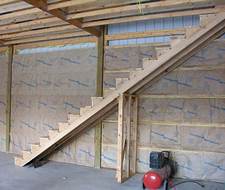
Stair stringers act as beams, where top is attached to an appropriate member by means of a Simpson LCS bracket (or equivalent) and bottom is resting upon a wood or concrete floor.
Looking at an exception 3 above rise and run, would cut triangles 4-1/2” deep into a 11-1/4 inch 2×12 stringer, leaving 6-3/4” of ‘meat’ remaining.
How far can a 2×12 stringer then span in a residential application?
Checking for bending only:
SQUARE ROOT OF [8 x Sm (Section Modulus of 1.5” x 6.75” x 6.75” / 6 = 11.39) x Fb (Fiberstress in bending, for #2 SYP = 750, SPF = 850, HemFir = 875, DFir = 900)] / (40 psf live load + 10 psf dead load) x 36” width stairs/2 (one stringer on each edge of stair width)
For SYP (Southern Yellow Pine) = 8.71’ (or 8’8”). This span is measured horizontal to ground and is measured from centerline of required bearing area at each end.
Checking for Deflection
Allowable = 104” / 360 = 0.289”
Maximum = (5 x (50 psf/12 x 1.5’) x 104”^4) / (384 x MOE x I)
MOE (Modulus of Elasticity) = 1,400,000 for SPF or SYP; 1,600,000 for DFir; 1,300,000 for HemFir
I = b x d^3 / 12 = 1.5” x 6.75”^3 / 12 = 38.44
(5 x 6.25 pli x 104”^4) / (384 x 1,400.000 x 38.44) = 0.177” <= 0.289” therefor OK
For greater spans, a 2×6 #2 can be applied alongside 2×12. Fb value of lesser member must be used (even though 2×6 has a greater individual strength):
Bending test:
SQUARE ROOT OF [8 x (11.39 + 7.5625) x 750] / (50 x 18”) = 11.24’ (rounding down to 134”)
Checking for Deflection
Allowable = 134” / 360 = 0.372”
Maximum = (5 x (50 psf/12 x 1.5’) x 134”^4) / (384 x MOE x I)
I = b x d^3 / 12 = 1.5” x 6.75”^3 / 12 = 38.44 for notched out 2×12 plus 20.8 for a 2×6
(5 x 6.25 pli x 134”^4) / (384 x 1,400.000 x 59.24) = 0.316” <= 0.372” therefor OK
Need to span even farther? Let’s add another 2×12 with a 2×6 on each side in center of tread. Center stringer supports twice load of outer stringers.
SQUARE ROOT OF [8 x (11.39 + (2 x 7.5625)) x 750 x 1.15] / (50 x 18”) = 14.258’ (171”)
But wait, where did 1.15 come from? When three members are combined or members are 24 inches on center of less, Cr (Repetitive member factor) is equal to 1.15.
Checking for Deflection
Allowable = 171” / 360 = 0.475”
Maximum = (5 x (50 psf/12 x 1.5’) x 171”^4) / (384 x MOE x I) I = 38.44 for notched out 2×12 plus 2 x 20.8 for two 2×6 = 80.04
(5 x 6.25 pli x 171”^4) / (384 x 1,400.000 x 80.04) = 0.621” > 0.475” therefor NOT OK
Even though this combination works for bending, it is beyond deflection limitations. Solution is to place internal stringers at third points.


