Build to Match the Pole Building Plans
Picture this, if you will…..
A monitor style post frame (pole) building. The center portion is 24 feet wide by 48 feet long with a 24 foot eave height. On each side of the center is a 12 foot wide “wing”.
The right wing is a roof 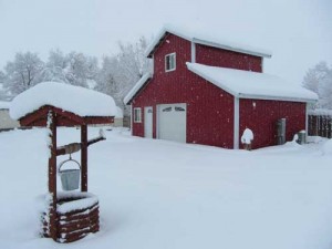 only – with a steel covered wall between it and the center portion. The left wing has its exterior walls enclosed, and is open to the center.
For those of you, fair readers, in the majority of the country, a structural permit to build could be obtained without the need for engineer sealed pole building plans (although I am not advocating going without one). Not so much where this building is to be – this particular client’s building is going to require engineering.
Here is where the fun kicks in, as the building is now constructed and the final inspection has been called for. This is what the field inspector found:
On the Left Wing the client’s builder put 2×10’s 16” on center going across to the posts on the main building in order to create a flat ceiling. The Building Inspector asked if they would put anything up in the top of the triangle which they said “yes, Christmas boxes”. The inspector will not pass final inspection as he said it is not designed to carry the weight.
The client asked his Hansen Pole Buildings’ Designer if the engineer could send a letter or something stating it would not affect the structural integrity of the building.
And…..they finished the wall between the left shed and the main building. The stick (stud) framed wall is supported only by the four inch thick concrete slab. The Building Inspector told them they needed 6” of concrete as 4” was not strong enough to carry the weight of the wall.
None of these things, by the way, was communicated to our design & drafting team, so was not incorporated into the engineer sealed pole building plans.
My rule of constructing an engineered building is follow the plans exactly and you won’t have issues with inspections!!
As for the 2×10’s, they would act as floor joists with a 40 psf (pounds per square foot) live load and a 10 psf dead load (at least for their part of the action). The unknown is, how are those joists being supported at each end? It appears a 2 ply 2×12 #2 DFir (Douglas Fir) beam might be able to adequately carry the loads, provided they were attached with proper connections.
Of course no consideration has been given for the amount of extra load being transferred to the columns and down to the footings. This is no small issue – as we are talking about 4000 pounds per column of added load!
Leading to the framed wall, which I am guessing is now carrying one end of aforementioned floor joists. Which makes it a load bearing wall. Which means it requires a six inch thick concrete footing.
In the end, my recommendation was to remove all of the non-engineered changes from the building, and call for inspection again. We can’t even make “suggestions” as to a fix or any other solution – those answers need to come from the Engineer of Record, and they do not come for free.


Was wondering if it is feasible and the approximate cost to put a concrete breezeway and stall floors in my 36×36 barn. Currently the barn has 5 stalls (12×12) a tackroom and a breezeway. We purchased the property a few years ago and are wondering if this is a viable option to improve our barn.
It should certainly be feasible. If you do not know of any concrete finishers, who could quote you a price, reach out to your local premix company and ask for a list of concrete contractors.