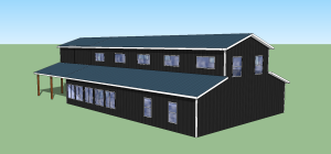
This is Day 3 in my discussion of building plans (i.e. blueprints) with today’s focus on the Interior “section” elevation. When you cut open an apple, what do you see? Just a flat one dimensional view of what is inside of the apple.  This is exactly what we do with the Interior Section on your building plans. For some people, this view is more difficult to “see”, as it is just a slice through the width of their building. If this page is too difficult for you to look at, it’s ok. There are “end” pages for all 4 sides of your building, and many of the pieces are shown on more than one page. You have lots of views to choose from, along with details to “zoom in” on the connection areas.
The interior section elevation shows the inside connections of the trusses to the posts. In our particular structural building style, we use double trusses for the interior bays and single trusses on the endwalls. All trusses are notched in for full weight bearing. This is the point in writing this blog where I usually anticipate questions on the merits of double versus single trusses, and also the pros versus cons of notching in trusses to the posts or hanging them off the sides of the posts. This is not the point of today’s discussion, so please look back (or stay tuned) for those particular topics. I have a lot to say on each of them!
The interior section elevation shows how many and what type of connectors are used to attach the trusses to the posts, and also the purlins to the trusses. If the building is very large or very tall, like riding arenas, large heavy plates and bolts are used to attach interior trusses to posts. These plates can be 18” long, 5 inches wide and a quarter inch thick! But again, this is for those really wide and tall buildings, or those with high wind speeds.
With sheds, interior rafter connections are shown, along with any special nailing if rafters are doubled. This view shows a generic drawing of a truss, as the actual trusses designed for your wind/snow/seismic and other features (height, width) must come from the truss company supplying the trusses. They also come with building specific drawings sealed by a truss engineer.
Girts are those horizontal members which support the wall sheeting, such as steel panels. This also includes OSB as a precursor for any non-structural siding such as vinyl or stucco. Some folks call the wall girts “wall purlins”, just as they also call the roof purlins, “roof girts”. It doesn’t really matter, as long as you are clear on what your plans are telling you to do with them, and you are using the Construction Guide to assist your assembly. The plans will show you how far apart to place the girts, as spacing is dependent upon the wind speed and exposure of your building, unless you purchase what is termed “commercial girts”. These girts are spaced every 2’ and are designed to have an insulation cavity, along with a mud sill at the bottom and a drywall “L” at the top so sheetrock can be screwed to top and bottom edges. Do you need commercial girts? Not if you are not insulating and drywalling your buildings, but some builders prefer to install girts and purlins all at 24” for ease of construction. You can always add more framing to your building. You just can’t do less than what the building code dictates for your jobsite.
A cut view of the poles with concrete depth, diameter and showing the spacing off the bottom of the hole (to be filled with concrete) is also shown on this view. If you have a building with two eave heights, such as a two story portion attached to a one story, there will be an interior section for each elevation.
Want to see a sample page?
Click here to view: https://www.hansenpolebuildings.com/sample-plans.htm
And come back tomorrow when we talk about page 4, Front and Rear Endwall Elevations.
Have a great day!


