What Kind of Trusses Are Pictured?
This question was posed by Hansen Pole Buildings’ Designer Doug. Photo isn’t of a Hansen Pole Building, probably raising questions in Doug’s mind as it looks rather foreign.
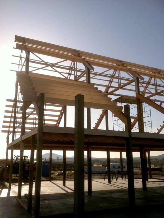
Only actual trusses in photo are in raised center portion of this monitor style building. Interior trusses were probably sold to building owner as being “double trusses”. In actuality this system has only a single truss placed upon each side of columns. These trusses, even though only inches apart, do not load share. They are only as strong as weakest individual truss. Between trusses, sticking up beyond top of top chords are paddle blocks (read about paddle blocks here: https://www.hansenpolebuildings.com/2012/05/paddle-blocks/) to attach roof purlins.
Monitor wings (or side sheds/lean-tos) have rafters placed each side of columns with paddle blocks as well. Second floor (aka loft) extends out into wing areas, although quickly loses functionality as headroom decreases close to eaves.
More headroom could have been garnered throughout entire second floor had trusses and rafters been positioned to allow roof purlins to joist hang into their sides. When placed as “top running” purlins, interior clear height decreases by purlin thickness. Positioning of roof trusses as lowered, below purlins causes builder to have to frame outriggers (or tails) above truss in order to support sidewall overhangs. Each paddle block makes for a purlin stagger and eliminates one’s ability to predrill roof steel panels. This adds to possibilities of roof leaks being created by each stagger point.
Other concerns exist in this photo. Where roof purlins overhang single end truss, attachment has been made with yet another set of paddle blocks. With an assumption overhangs will be enclosed, this allows for outside air to enter in spaces created between purlins. This decreases efficiency of dead attic space airflow from eaves to ridge.
Solid blocking should be placed between end overhanging purlins to provide continuity of a load path from roof diaphragm to ground. As being built, load path has been divided.
Perimeter beams in this photo show to be inset between the columns. My curiosity wonders how they adequately attach? Your guess is as good as mine.


