Tag Archives: X bracing

Who is Responsible for Design of Permanent Truss Bracing?

Who is Responsible for Design of Permanent Truss Bracing?

This article was triggered by an email questioning truss bracing from Hansen Pole Buildings’ client JASON in WELLINGTON who writes:
“My inspector is telling me that the truss documents take precedence over the building plans. I told them the building plan has the x bracing and the t-bracing. He didn’t care. He wants all the shown bracing from the truss documents. I am not sure what to do. I think the inspector is being ridiculous.”

In my humble opinion this inspector has an absolutely incorrect opinion. Included in Hansen Pole Buildings’ Construction Manual are engineer sealed letters from two significantly large truss plate manufacturing firms, clarifying who has responsibility for design of Permanent Truss Bracing. These companies typically supply engineer sealed drawings for metal plate connected wood trusses (MPCWT) manufactured by purchasers of their truss plates. Copies of these letters should be provided to this inspector.
Inspector can also be given this link (to ANSI/TPI 1-2014): https://static1.squarespace.com/static/53442b51e4b072e71999c8c5/t/56d9d1038259b560ad3a0821/1457115397817/ANSI_TPI+1-2014StdONLY-WEB_WP.pdf

Included in ANSI/TPI 1-2014 (incorporated by title in Building Codes) are:

In Section 2.2 DEFINITIONS

Building Designer: Owner of the Building or the Person that contacts with the Owner for the design of the Building Structural System and/or who is responsible for the preparation of the Construction Documents. When mandated by the Legal Requirements, the Building Designer shall be a Registered Design Professional.”

Permanent Building Stability Bracing: Lateral force resisting system for the Building that resists forces from gravity, wind, seismic and/or other loads.

Permanent Individual Truss Member Restraint: Restraint that is used to prevent local buckling of an individual Truss chord or Web member due to the axial forces in the individual Truss member.

Registered Design Professional: Architect or engineer, who is licensed to practice their respective design profession as defined by the Legal Requirements of the Jurisdiction in which the Building is to be constructed.”

And be pointed to Section 2.3.2 Requirements of the Building Designer

Section 2.3.2.3 Review Submittal Packages:The Building Designer shall review the Truss Submittal Package for compatibility with the Building design. All such submittals shall include a notation indicating that they have been reviewed and whether or not they have been found to be in general conformance with the design of the Building.

(Author’s note – General Note 9, Sheet S-0 of Registered Design Professional sealed plans provided to client, specifically addresses Section 2.3.2.3 above.)

Section 2.3.2.4(c) All anchorage design and connections to the Structural Elements and the Permanent Building Stability Bracing required to resist uplift, gravity, and lateral loads.

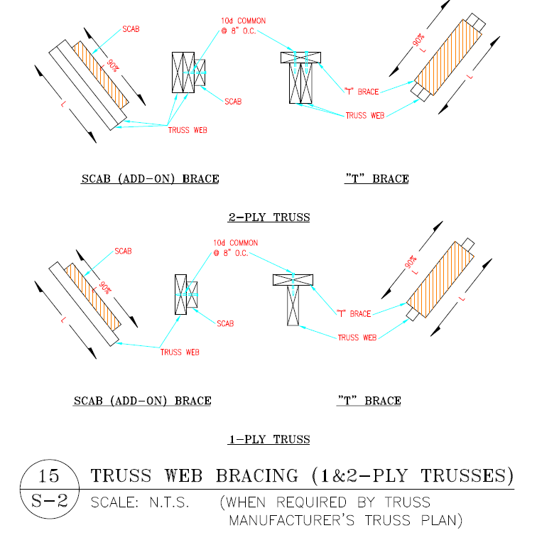
Section 2.3.3 Requirements for the Permanent Member Restraint/Bracing of Truss Systems.

Section 2.3.3.1 Method of Restraint. The method of Permanent Individual Truss Member Restraint/Bracing and the method of anchoring or restraining to prevent lateral movement of all Truss members acting together as a system shall be accomplished by:

Section 2.3.3.1.3 Project Specific Design. A project specific Truss member permanent Lateral Restraint/bracing design for the roof or floor Framing Structural System shall be permitted to be specified by the Building Designer or any Registered Design Professional.

Building Officials and inspectors have a veritable mountain of materials referenced by Building Codes. Tremendous volume of these references becomes more than any one person (or small group of persons) can possibly know completely contents of all. It would be unrealistic to expect otherwise.

80 Foot Span Wood Trusses

Setting 80 Foot Span Wood Trusses

Here is the question asked by CHAD in EVANSVILLE:

“What is the best way to hang an 80′ wooden truss? The company I work for is building 80×120 pole barn for one of our customers. The trusses are kicking our butt.”

Before you even think about getting started, you will want to read this article: https://www.hansenpolebuildings.com/2013/12/wide-span-trusses/.

My first adventure in setting 80 span metal connector plated wood roof trusses was on a horse riding arena for Percy Freeman in Oregon. You can read about the misadventures here: https://www.hansenpolebuildings.com/2014/03/wide-span-trusses-2/, as it was quite a saga!

I have learned a lot since Mr. Freeman’s building and would approach the solution much differently today than 30 years ago.

In your case, I would imagine you are placing the 80 foot trusses either every two or four feet on top of truss carriers. You will want to fully concrete encase the embedded corner and endwall columns, so there is an adequately stable foundation. Firmly brace the endwall columns, to prevent (as much as possible) and sway in the lengthwise direction of the building.

I’d look at bringing a large crane in, so at least 12 feet of roof could be fully assembled on the ground (or at least to the point of being ready to insulate and steel the roof. Install all required permanent bracing along the bottom chords and webs of the trusses. I would also X brace in line with each endwall column, from bottom chord of the endwall truss to top chord of the truss at 12 feet and from the bottom chord of the truss at 12 feet back to the top chord of the end truss. Confirm all trusses are plumb before attachment of the X bracing. If the individual member of the X braces cannot be nailed directly to truss vertical webbing, they need to be connected together where they cross. If this is the case, to prevent buckling in the narrow direction, install one member with the narrow face towards the ground, the other with the wide face towards the ground.

Next install bracing across the upper side truss bottom chords in a zigzag fashion, beginning at the corners of the building. These will be left permanently. Repeat this across the tops of the purlins, however these will be removed prior to installation of the roof insulation and steel roofing.

Raise the entire section into place and install the first few panels of roof steel. This section will give a steady anchorage point for the installation of subsequent trusses, either in sections or individually. Make sure to brace off each truss or section of trusses as they are installed.

The Registered Design Professional contracted for the design and inspection of the temporary and permanent bracing systems may desire additional bracing beyond the above. However I would look upon this as a minimum for successful and safe installation.

Temporary Truss Bracing

The Importance of Temporary Truss Bracing

Back in my early days in the prefabricated metal connector plated truss industry, one of my clients was the congregations of a church along Highway 95 in Hayden, Idaho. The project was for an entirely new building, with the work being done by primarily volunteer help, under the supervision of a carpenter with more decades of experience under his belt than even my Father or my five Uncles.

The design called for a large central clearspan comprised of low slope trusses with a raised heel. (For more reading on raised heel trusses: https://www.hansenpolebuildings.com/blog/2012/07/raised-heel-trusses/)

Surrounding this on three sides were areas with monoslope (sloping in one direction away from the main span) trusses, which were placed first.

Once the walls for the central portion were framed, the supervisor called for delivery of the main span. As the trusses were very large, they paid extra for our crane truck to individually place the trusses (good idea). All of this was accomplished on a chilly windless day in mid-January, without a hitch. Our crane truck had hardly completed the 15 minute drive from the building site back to our manufacturing plant, when we got “the call”…..the roof had collapsed!!

I high-tailed it out to the church, to find the experienced carpenter shaking his head. The rear of this set of trusses had been braced against the previously framed roof behind, with temporary truss bracing. Before putting permanent bracing in place, the contractor had removed the temporary bracing. He said he knew it was in trouble the moment he pulled out the last nail, and in the blink of an eye, it was scrambled trusses on the ground!

From the pole building photos attached from a recent project (not the church), it is impossible for me to determine if the trusses and their attached purlins were in place or being placed when things went bad. What I can tell is this – there is no bracing of any sort to be found in this assembly which would have kept it from racking or toppling. The temporary truss bracing is AWOL.

What would have helped to prevent this pain?

X Bracing
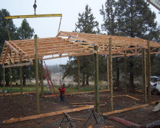
An X Brace, or braces, between the top chord of one pair of trusses and the bottom chord of the other pair would have prevented toppling (the larger the span, the greater the need for more than a single X). Also, temporarily nailing some of the wall girts to the tops of the roof purlins in diagonal fashion would have prevented the assembly from racking.

The Wood Truss Council of America (WTCA) www.WoodTruss.com and the Truss Plate Institute (TPI) www.tpinst.org have prepared a summary sheet BCSI-B10 “Post Frame Truss Installation and Bracing”, which is included in the Hansen Pole Buildings’ Installation Manual, and should be provided to anyone who is assembling a pole building using prefabricated wood roof trusses.

Trusses are very, very strong when properly installed and braced in the vertical direction for which they were designed. By using care and caution, during handling and installation, they will perform admirably for generations.

Can I Remove Bottom Chord Bracing?

Truss Bracing In The Way?

Thirty three years ago, when I first dipped a toe into the post frame industry, roof truss bracing was pretty much an afterthought. Even though I came to pole buildings from the prefabricated metal plated truss business, bracing (especially of bottom chords) was pretty much a subject left up to the person doing the building.

Back then, it was not unusual to see 40 foot and wider spans, with absolutely no bracing at all between pairs of trusses spaced every 10 to 14 feet.

Apply a bit of a load to those trusses, from either wind or snow, and the bottom chords begin to form an “S” curve, as they are buckling in the weak direction.

Bottom Chord BracingSolution to the S? Add bracing.  

Modern engineered prefabricated roof trusses do take into account and recommend bracing. Oddly, the drawings will specify what appears to be a single 2x lateral brace, on truss spacings greater than 10 feet. Why I say “odd” is because a single 2x brace, of any size, which spans over ten feet, will buckle in the weak direction just like the trusses did.

Roof truss bottom chord bracing, properly designed and installed will not only keep the trusses in plane (standing upright), but will also brace the endwall columns. By the use of strategically located X bracing, loads from the endwalls and truss bottom chords can be transferred into the roof diaphragm.

A “load path” must be created from one end of the building, to the opposite end.

For example: a 60 foot long building, with five equal sidewall column spacings (or bays) of 12 feet each. Bays one and five are braced with X’s from the end truss bottom chord to the top chord of the second pair of trusses; and from the end truss top chord to bottom chord of second pair of trusses. Common sense says this is a fairly rigid bracing system as both directions take the loads into the plane of the roof.

In bays two, three and four, lateral bottom chord bracing is applied in the plane of the bottom chords. This bracing is anchored to the relatively “stiff” first and fifth bays.

Let’s complicate matters….

Imagine bay #3 has a large door, through which building owner desires to drive a vehicle in, place on a car lift and raise it so it is between the pairs of trusses. Wonderful, until the vehicle hits the truss bracing.

Oops….

Solution: remove the lateral bottom chord bracing in bay #3 and change the bracing in Bays #2 and 4 to X bracing. Every truss is still braced in both directions, and the load between the second and third pairs of trusses is transferred by the roof diaphragm.

If the building is designed by a RDP (registered design professional – architect or engineer), it is essential this modification be ideally made in the initial bracing design, so as not to incur additional engineering fees for a change.

Obviously this solution will not work to remove lateral bottom chord bracing in adjacent bays, but it does afford some added flexibility in design solutions.