Tag Archives: wind loads

San Diego County, Wind Speeds, and Wet Set Column Brackets

This Wednesday the Pole Barn Guru answers reader questions about whether or not Hansen has sold a building in San Diego County, CA, a building with a design wind speed of 150mph, and a recommendation for use of PermaColumn wet set brackets.

DEAR POLE BARN GURU: Have you sold pole barns in  San Diego County, CA? KEN in RAMONA

DEAR KEN: It is a challenge to find any county in America without a Hansen Pole Building (or several) in it. We have provided close to two hundred fully engineered post frame buildings to our clients in California – including in San Diego County.


DEAR POLE BARN GURU: Hello, Our codes recently changed to 150 mph plus for wind load and I want to build a post frame home. Do you have engineering to satisfy that for any pole barn kit/trusses/etc that you may offer for sale? I’ve attached a file and have the spacing showing in red squares as 10 ft-10 ft-8 ft-10ft-10ft. Thanks. JEFF in MARIANN

DEAR JEFF: Thank you for your interest in a new Hansen Pole Building. We are able to engineer for design wind speeds in excess of 200 mph. One of our Building Designers will be reaching out to you shortly, or call 1.866.200.9657 for immediate assistance.


DEAR POLE BARN GURU: Hello Mr. Mike. I have attached our plans and had a couple questions. What do you think about perma column brackets for this type of build? What do you think about our plans in general? Any issues? We are building in south Georgia. Thank you so much. JASON & ERIN in THOMASVILLE

DEAR JASON & ERIN: Your plans did not arrive as an attachment, so I am unable to speak to them. If your concern is with properly pressure preservative columns prematurely decaying when embedded in ground, then Permacolumn Sturdi-Wall Plus brackets are indeed your best design solution. Unlike other, cheaper, brackets, these actually will resist moment (bending) forces and have ICC-ESR approvals as being Building Code conforming. For extended reading on Sturdi-Wall Plus brackets: https://www.hansenpolebuildings.com/2019/05/sturdi-wall-plus-concrete-brackets/

Please forward your building plans, site address and best contact number to Caleb@HansenPoleBuildings.com, as our team can evaluate them for practicality as well as providing a firm price quote.

Does 24 Gauge Steel Make Sense?

Does 24 Gauge Steel Make Sense?

Reader TED in INDIANAPOLIS writes:

In terms of longevity, long term resistance to weather damage and price difference, does a painted AZ50 galvalume R-panel with PBR-leg in 24 gauge (min. .0239″) make more sense than a 26 gauge panel?”

Mike the Pole Barn Guru answers:

In all reality, even 26 gauge steel is far thicker than you need.

American Iron and Steel Institute (AISI) has published accepted measurement standards for steel thickness. 29 gauge steel (post frame industry’s standard) has an average .0172 inch thickness (with a .0142” minimum). 28 gauge steel has an average.0187” thickness (minimum .0157”) and 26 gauge is .0217” (minimum .0187”).

These thicknesses are all measured prior to any primer or paint applications.

Steel coil is sold by steel mills or wholesalers to roll formers by weight. Roll formers sell finished formed roofing and siding by lineal foot. Roll formers make their greatest profits by ordering steel coil as close to minimum thickness as possible, as it produces more lineal footage per pound. When roll formers order steel coil, they place orders by minimum steel thickness (e.g. .0145 min would be 29 gauge).

To give a perspective on steel thickness differences, from 29 gauge to 26 gauge difference in thickness is .0045 of an inch. A sheet of 20# paper measures .0038 of an inch. Roughly speaking, thickness differences between these two gauges is about a sheet of notebook paper! In comparing minimum thicknesses, although a sheet of paper may not sound like much, 26 gauge steel is 31.7% thicker than 29 gauge, based upon minimum thicknesses.

Now more importantly – how much load will a steel panel carry? A post frame building’s “weak link” is not load carrying capacities of its steel roofing and siding, it will be found somewhere in its underlying framing system. Taking a look at span tables provided to us by Union Corrugating Company for their MasterRib® (MasterRib is a registered trademark of Union Corrugating Company) panel, when spanning 24 inches, 29 gauge will support a live load of 112 pounds per square foot (psf) and 26 gauge 150 psf. These differences equating basically straight line with thickness differences.

Unless a building is at a snow ski resort, roof snow loads are probably not going to approach 112 psf, but what about wind loads? This same 29 gauge MasterRib® panel will support 118 psf in wind load, roughly equal to 214 miles per hour! For a perspective, highest officially recorded wind speed measured in United States was 231 mph. It was logged on 12 April 1934, at New Hampshire’s Mount Washington Summit Observatory.

But, what about hail? Please read https://www.hansenpolebuildings.com/2020/11/steel-roofing-hail-dents/ and https://www.hansenpolebuildings.com/2020/11/how-to-minimize-possible-hail-damage/.

But, but – oil canning?

Oil canning is a visible, wavy distortion affecting cold-rolled metal products. It’s seen in metal panel’s flat areas, and can be characterized as a moderate aesthetic issue. Typically, rippling, waviness, or buckling is especially seen in a metal roof or wall’s broad areas.  Most popular 36 inch net coverage, through screwed, steel panels are manufactured with high ribs every nine inches and two low profile ribs in between. These low profile ribs almost guarantee no eye-visible oil canning will occur.


Bottom line is… do you need 26 gauge steel?  No, you probably really don’t.  29 gauge is going to do everything you need it to do.  When would you need 26 gauge steel?  If you are going to purchase an all steel building and have five feet between your purlins and seven feet between your girts.  On a wood framed building with half those spacings or less, it’s almost always just overkill.  Beware those who try to sell you something you don’t really need.

Bracing Site-Built Trusses for Lateral Loads

Bracing Site-Built Trusses For Lateral Loads

Reader in SHINER writes:

I am building a gambrel style barn, 30×80, in two directions, in plan view, it looks like a cross. I am building the trusses based on an LSU publication, giving sizes of structural members, etc… I have built several structures before, not a gambrel style barn though. My Question, Guru, how do I brace the trusses for lateral/wind/racking/diagonal loads? I want to do an exposed ceiling of 2×10’s T&G, and am worried about how to brace the trusses so they don’t fold over like a deck of cards during and after construction. Surely the nails don’t provide all the lateral bracing? I’ve seen too many leaning barns over the years to know that nails alone don’t provide sufficient wind load protections. How are the trusses braced, one to the next, so they don’t fold/roll over? Your help is so appreciated, Thank you.”

Mike the Pole Barn Guru writes:
Even with my decades of truss industry experience, I wouldn’t begin to think of field constructing 30-foot span gambrel trusses. 

I did review LSU’s “truss” design (these are actually rafters not trusses), it is from 1988 and includes this disclaimer:

“This site makes available conceptual plans that can be helpful in developing building layouts and selecting equipment for various agricultural applications. These plans do not necessarily represent the most current technology or construction codes. They are not construction plans and do not replace the need for competent design assistance in developing safe, legal and well-functioning agricultural building system. The LSU Agriculture Center, the Mid-West Plan Service, the United States Department of Agriculture and none of the cooperating land-grant universities warranty these plans.”

Several problems – no design roof or wind loads are incorporated in their design and design values for Southern Pine lumber were down graded as much as 30% in 2012 https://www.hansenpolebuildings.com/2012/06/southern-pine/

Any permanent roof truss/rafter bracing system should be developed only by a Registered Professional Engineer. Given LSU’s information is highly out dated, should you wish to continue upon this path, I strongly urge you to reach out to a competent Registered Professional Engineer to design a structurally adequate system, including a permanent bracing system you can rely upon.

Condensation Control, Load Requirements, and A Sloped Site

This week the Pole Barn Guru answers reader questions about condensation control in Spokane, WA, the availability of a hipped roof design to meet wind and snow loads, and planning for a post frame build on a sloped site.

DEAR POLE BARN GURU: I’m in Spokane, WA– a semi-arid region, and I had a question about using metal roof panels with prefabbed integral condensation control, such as Condenstop, along with a double bubble reflective barrier. I have a few left over rolls of the reflective barrier that I can use and would only need to buy an extra roll or two for our prospective 36×36 post frame building. Would it be ok to use both without trapping moisture between the 2? Or, should I only use 1? Building will have continuous soffit venting on both eaves and ridge venting as well. The building will be used in-part to store food-crop and will be temperature-controlled during all seasons, and has drywalled ceilings. Therefore, I’d like to insulate to the max. Was thinking spray foam between the purlins and also fiberglass batts? MATT in SPOKANE

DEAR MATT: I was born and raised in Spokane, owned a house on Newman Lake until just a couple of years ago. In the 1990’s I was the area’s most prolific post frame builder – one year we erected over 200 post frame buildings in Spokane county alone!

Let’s look at doing this right, and not spend money just to spend money.

Spokane is Climate Zone 5A. 2021 International Energy Conservation Code requirements (IECC) are R-60 roof, R-30 walls

Roof: 16″ raised heel trusses, vent overhangs and ridge in correct proportion, roof steel with Integral Condensation Control, blow in R-60 of granulated Rockwool.

Sell your reflective barrier on Craigslist or Facebook Marketplace.

Walls: Steel siding, Weather Resistant Barrier (Tyvek or similar), 2×8 commercial bookshelf girts, R-30 Rockwool batts, well-sealed vapor barrier.


DEAR POLE BARN GURU: In your blog you state that hip roof style the strongest against high winds. as I live in tornado alley wind and snow drifting are concerns of mine and would like my building design to be highly resistant to these forces. Why can I not find examples of this roof style on your web site? Is the gambrel style the closest you come to this design? CARY in RAYMOND

building-plans
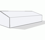
DEAR CARY: Very few clients have been willing to make an extra investment into full hip roofs, explaining why our website has no photos of them (we do rely upon our clients to provide photos). We can engineer traditional (and most cost effective) gable roof designs with wind speeds in excess of 200 mph. Our Building Designers can incrementally adjust design wind speeds to allow you to make decisions to best meet your concerns and budget.

While most roof truss manufacturers meet Code requirements for unbalanced (drift) snow loads, we are one of few (if not only) building providers who also design roof purlins appropriately to resist these same loads. This typically results in purlins closest to ridge to be either more closely spaced and/or larger in dimensions.


DEAR POLE BARN GURU: We purchased property in north central Tennessee and are planning a post frame barn for a RV and SUV storage and then later adding a post frame home as our forever home. Building site has about a 5 – 10 degree slope. Can you recommend some reading material, books, articles, how-to’s that I can learn and start making some educated research and decisions? thanks. JEFFREY in PRAIRIEVILLE

DEAR JEFFREY: A plethora of options are available for sloped sites. They can be excavated to create a “walk-out” or “daylight” situation. I was faced with this situation on one of my personal buildings (albeit with a more extreme slope): https://www.hansenpolebuildings.com/2019/05/solving-massive-pole-building-grade-changes/
Sites can also be built up: https://www.hansenpolebuildings.com/2020/01/supporting-fill-when-considerable-grade-change-exists/
And there is always an option of “stilts” https://www.hansenpolebuildings.com/2020/03/stilt-home-barndominium/
For research, a great source of information is always to navigate to www.HansenPoleBuildings.com, go to SEARCH in upper right corner, type in whatever topic you are looking for information on (e.g. BARNDOMINIUM) and hit ENTER. Over 2000 articles are available, covering a broad myriad of subject matter.

Whatever route you do ultimately pick, fully engineered post frame is likely to be your most cost effective and energy efficient structural design solution.


Secure Doors, Soffits, Wind, and Sliding Door Tracks

This Wednesday the Pole Barn Guru answers reader questions about a secure replacement for sliding doors, soffit kits, a singular concern of wind, and replacing tracks for a sliding door.

DEAR POLE BARN GURU: I need to replace two 9.5 ft wide by 8 feet high sliding doors on my pole barn. The current doors are a wood box frame with a piece of siding. I am looking for something secure so I can keep tools and stuff inside. I also need help with a soffit question. Is there a steel/aluminum facing and soffit kit that I can use to make this easier without much cutting and metal bending work? CHRISTOPHER in GROVE CITY

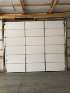
DEAR CHRISTOPHER: If you are looking for security you should consider upgrading to sectional steel overhead doors. Sliding doors are not secure and do not seal tightly (as you have probably determined).

Metal soffit panels are available in 12′ lengths, both vented and unvented, they will need to be cut to width of your overhang, however properly installed, both cut edges will be covered by steel trim. Fascia trims are manufactured as an “L” with long vertical leg being height of your building’s fascia board plus 1/2″ for soffit thickness. Shorter leg will be 1-1/2″ with a hem. This will cover cut ends of your soffit panels as well as any exposed fasteners. Both soffit and fascia are available in a plethora of colors.


DEAR POLE BARN GURU: My only concern is wind…

DAVID in SYRACUSE

DEAR DAVID: We are concerned about all climactic conditions, with every building we provide. This is one of many reasons we made a determination long ago to only provide fully engineered buildings – as it is an assurance to our clients every component and connection has been reviewed for structural adequacy.

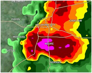
Keep in mind, Building Code load requirements are bare minimums and are no guarantee buildings will not suffer severe damage, if loaded to maximum design loads. Codes are designed to protect human life, not necessarily to keep buildings standing usefully. I would encourage you to explore design wind speeds greater than Code minimums, as often they come with very small extra investments. We can design and have engineered buildings capable of surviving EF-3 tornadoes (wind speeds up to and including 208 mph).

Important with any design for wind, is an understanding of wind exposure. For extended reading, please visit: https://www.hansenpolebuildings.com/2012/03/wind-exposure-confusion/


DEAR POLE BARN GURU: Have a 1970 Quonset hut on our property and the doors are the sliding doors. The bottom track for the doors are all bent and beat up that the beginning of the tracks and the doors won’t stay on their tracks anymore. The length of the existing tracks are 101.5 inches – and I need replacement guides/tracks so the doors will actually stay on the tracks when it gets windy and stop popping off at the bent end. Where does one acquire those replacement track/guides for the existing huge sliding doors. Thank you. DAWN in HARRINGTON

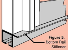
DEAR DAWN: You have discovered why ‘modern’ sliding doors use a bottom door girt with a slot, where as door slides open, a building mounted guide keeps doors tight to your wall. My best recommendation would be to have a machine shop fabricate up new bottom tracks – if you only have to replace them once every 50 years or so, it would prove to be a sound investment.

SIPS for Barndominiums

It has only been five years since I first opined about using SIPs for post frame building construction: https://www.hansenpolebuildings.com/2015/02/sips/. Since then, post frame homes (frequently referred to as barndominiums) have become quite the rage. Easily half of Hansen Pole Buildings’ inquiries are now for some combination of living space!

I had recently done some further research on SIPs and actually acquired pricing, reader STEPHEN from RAPID CITY was evidently thinking on a like-minded path when he wrote:

“I am a CAD student at Western Dakota Tech in Rapid City, SD and have been thinking about a way to use post-frame buildings as a cost-effective way to create very energy efficient (essentially passive house level insulation and airtightness) residential housing.  What do you think of the possibility of attaching appropriately sized SIPs to the outside of the posts instead of other sheathing and using their strength to do away with girts all together? I have seen SIPs advertised as being used this way with timber framed or post and beam construction (neither are cheap) but not with post-framed buildings.  The idea would be to have thick enough SIPs to not need internal dimensional lumber in the SIP thereby removing thermal bridges, but having it still be strong enough for racking and wind loads.

I know that the costs for SIPs mostly comes from the manufacturer having to essentially custom make each piece.  In this application the SIP panels could be made as rectangles that are as wide as your center to center post distance and as tall as is convenient. Any angled pieces for gable ends and any fenestrations could be cut on site, reducing SIP manufacturing costs.  The SIPs also would likely not have to have much dimensional lumber built into the SIP because it is just holding up itself and windows, not the whole building thereby drastically reducing your thermal bridging. You could also foam seal between the SIP panels to provide air sealing (which I believe is standard for SIPs anyway.)

I would think that you could either use thick enough SIPs to provide all of your insulation and just leave the posts exposed on the inside, or you could use a SIP that was just thick enough to, structurally, take the place of girts and sheathing and frame the space between the posts with 2x4s 24” o.c. flush with the inside of the posts and use fiberglass batts in that space.  

The first technique has the advantage of not needing to do any extra internal framing, but you do have to deal with the posts in your living space.  In addition, if you want to run any electrical to the inside face of any of those walls you either have to be ok with running it in conduit on the face of the wall or you are getting back to specially made SIPs with electrical chases.  The advantages of this technique over your suggestion of bookshelf girts and sheet insulation on the interior is that it doesn’t require interior framing (girts or traditional) and no need to glue drywall but the cost of the thick SIPS, even generic ones, might outweigh those advantages.

The second way of doing it does require extra framing and if your outside SIPs are air sealed you would have to be careful about using a moisture barrier on the inside of the wall (like you normally would in a heating climate) as you wouldn’t want to trap moisture in that space.  The advantages of this system over your bookshelf girts and sheet insulation is, again, no gluing of drywall, normal attachment systems for electrical boxes and cables, and the internal framing being slightly cheaper than full 2×6 girts. Again, the cost of the SIPs might make those advantages moot.

Finally, with either style, you could use a traditional (for post-frame buildings) ceiling with blown insulation above and a vented attic space or you could have full roof panel SIPs built with internal structure to span between your trusses, leaving them exposed inside, and get rid of your purlins as well (for both purlins and girts you would probably have to have some temporary bracing while the building is being built.)

What do you think? Have you heard of anyone doing something similar? Does this sound like it would be a viable way to get very high insulation and air sealing on the cheap?”

Mike the Pole Building Guru responds:

Thank you for your well thought out question, it is evident you have read some of my articles. I hope they have been informational, educational and/or entertaining.

I am usually a guy who jumps all over some brand new technology. My construction business had a website back in 1995 when there were only roughly 23,500 world-wide. This was not long after I had erected a post frame shouse (shop/house) for myself, not realizing there was such a thing as a barndominium. My first attempt utilized ICF blocks on two walls and a portion of a third to compensate for digging away a 12 foot grade change.

Getting on track, I have always thought SIPs would be “cool” as in neat, fun and interesting. It has only been recently I have been able to get some solid costs back on their use.  I approached this design solution from an aspect of eliminating all except columns, roof trusses, essential truss bracing and steel skin. I looked at this as applying SIPs to column exteriors and used a 36 foot wide by 48 foot length with 10 foot high walls. In order to span 12 feet between columns and trusses I was looking at R-52 panels. Wholesale raw cost difference (after eliminating typical wall girts and roof purlins) would add nearly $30,000 plus freight to this building. It would also require a crane onsite to place panels and some sophisticated fastening systems to attach SIPs to the framework.  It is relatively easy to achieve similar insulating values and air sealing for far less of a cash outlay.

Can it be done? Yes. Should it be done? Not if return for investment is a consideration.

Anyone who can design an overall cost effective post frame building design solution with SIPs, I am all ears and eyes to hear and read about it. Until then, for those who just want to be neat and different without cost as a factor, it might be a great system.

What an Engineer of Record Does for a Post Frame Building Part II

Continued from yesterday’s blog, an article by Jesse Lohse in SBC Magazine:


System Design

  • Understand Load Path
    • Gravity
    • Lateral
    • Uplift
    • MEP conflicts
  • Initial Designs
    • Roof System
    • Walls
    • Floor System(s)
    • Foundation
  • Broad Analysis for construction documents

System Design

Once an initial conceptual design is complete, an engineer will turn their attention to system design in a top down manner. An understanding of the structure’s load path is imperative with specific considerations given to gravity loads, lateral loads, and uplift on the various elements within the structure. Once the engineer has a general idea of the structure’s load path, they will begin initial designs of various structural systems. Working from the top down, engineers will produce initial designs first for the roof system. Then the walls including the gravity and lateral force resisting systems and any required beams and columns will be designed followed by the floor systems and repeated as many times as necessary, dependent on the number of levels and different unit types in the structure. Once the roof, walls and floor system has been designed attention will turn to the foundation and footings, leveraging information from the soil report derived in conceptual design. This broad analysis information is compiled into initial structural construction plans.

Element Engineering

  • Accurate dimensions
  • Specific member analysis
  • Coordinate geometry defined in CAD
  • Analysis model created (SAP 2000, STAAD, RAM, etc)
    • Dead loads
    • Live loads
    • Wind loads
    • Seismic loads
  • Internal forces
    • Axial forces
    • Bending moments
    • Shear force
    • Drag force
    • Combined forces
  • Initial Member Sizing

Element Engineering

The element engineering phase begins with the engineer ensuring accurate dimensions for the various portions of the construction project through geometry coordination as defined in 2D or 3D CAD software. Trusting the dimensions are accurate, the engineer will begin specific member analysis for the defined spans, such as calculating roof loads that are transferred to exterior and interior bearing walls. The lateral force resisting systems generally require the most engineering time combine with window and door perforations that require headers and beams. This analysis combines gravity, wind uplift and lateral loads paths. This load path analysis will also be applied to the floor system and foundations, giving the engineer a general idea of the variety of loads within the structural elements and where additional attention will be required in subsequent design phases. To aid in this analysis, engineers will use specific software applications geared towards structural design such as SAP 2000, STAAD and/or RAM. This analysis software will allow the engineer to apply a variety of loads including dead, live, wind and seismic. As a function of this analysis, the engineer will be able to determine axial forces, bending moments, shear force, drag force and the combined forces. Once the forces have been determined, the initial member sizing can commence, allowing the engineer to establish a ‘rough draft’ to further refine in downstream design steps.

Iterative Design

  • Design to code
  • Redesign Analysis model
    • Incorporate more accurate load paths
  • Fine Tune Final Designs

Drafting

  • Create structural plans
  • Fully detailed

Iterative Design and Drafting

Engineer sealed pole barnEngineers use an iterative process to fine tune the various elements into final structural element designs. Think of this as repetitive in nature working toward the ultimate goal of an efficient design that meets the variety of requirements the structure’s configuration places on the path that the applied load will need to take to get to the ground. The engineer starts with a broad understanding of the loads on individual elements and narrows the focus until each element and ultimately the entire structure is designed to safely transfer all loads, meet code requirements and provide an acceptable solution that can be signed and sealed. Through this process the load paths are accurate, specific and reliable. With the accurate load paths, drafting can be completed with fully detailed structural plans available for construction. 

Construction Administration

  • Review submittals
  • Obtain approvals
  • Prepare schedules
  • Monitor construction
  • Perform site inspections

Construction Administration

Further in the construction process, the engineer is often called upon to review RFI and deferred submittals, obtain code approvals or prepare construction schedules. Certain products, such as roof trusses, are considered a deferred submittal. This means the engineer allows the designs to be created by others and sealed by a specialty or delegated engineer.  Those sealed designs are reviewed by the EOR and either approved for manufacture or returned for revisions. Beyond review of conformance to the structural design, engineers will also monitor construction progress on behalf of the client and will often perform site inspections to make sure the construction process is progressing and installation of products is without errors. 


Mike the Pole Barn Guru comments:

Whew! That’s a lot the Engineer of Record does in the design of a post frame building. This whole process takes time and sometimes even I can get impatient while waiting for building plans to be produced and signed by the Engineer. But I know given adequate time the plans will be accurate and result in a beautiful post frame building.

Optimum Aspect Ratio of Length and Width

I suppose I inherently knew the answer to the optimum aspect ratio of length and width for post frame construction, but never really sat down to write about it. Well, reader JEREMY in EFFING has an inquiring mind and wants to know:

“In general terms is there an “optimum” aspect ratio to gain the best strength and minimize costs of construction? I.E.: if you are looking at around 3,200 square foot of space is it “better” to 24′ X 136′, 30′ X 104′, 40′ x 80′, 48′ x 64′, or 54′ X60′. I assume the 24′ width may require a division wall at 68′ to help carry the long wall wind loads so I doubt it is economical, and the 54′ building would require heavier trusses and posts.”

Let’s begin with what is usually the most cost effective dimension for length – multiples of 12 feet (24, 36, 48, 60, etc.) as well as width (multiples of 6 feet).

Arena BuildingWorking from the 3200 square foot benchmark this would give 24’ x 132’; 30’ x 108’; 36’ x 84’; 42’ x 72’; 48’ x 72’ and 54’ x 60’ as the ones which should be the most cost effective dimensions. The closer width and length are to each other, the lower the shear forces which must be carried by the roof.

At 5.5:1 the 24’ x 132’ building will, in all probability, require interior shear provisions – knocking it out of contention. Depending upon wall and roof height, wind speed and exposure at 3.6:1 the 30’ x 108’ might have some of the same challenges as well. When buildings become long, tall and narrow, high loading conditions can result in the need to reinforce sections of the roof and endwalls with structural sheathing besides the traditional steel.

The assumption the “54’ building would require heavier trusses and posts” is only partially correct.

Yes, the trusses may be fabricated from higher grade or larger dimension lumber and have more internal webbing. However, in many cases the added cost of each individual truss being ‘heavier’ is less than having to invest in a greater quantity of smaller span trusses.

Building columns happen to be very strong in compression (ability to withstand downwards forces). The larger span truss will probably not require larger columns due to roof snow and dead loads, and the stiffness of the roof in a small aspect ratio may offset the wind load placed on the extra height of the truss.

About Hansen BuildingsThe real answer here is we are talking about differences of cents per square foot, not dollars. Plan your new post frame building dimensions to best meet your needs for how you will be utilizing the building not only today, but potentially in future years. Good planning will always end up being the optimum for the dollars invested!

Tornado! What We Didn’t Learn in Moore

Tornado! What We Didn’t Learn in Moore

Moore OK Tornado RadarOn the afternoon of May 20, 2013, an EF5 tornado, with peak winds estimated at 210 miles per hour (mph), struck Moore, Oklahoma, and adjacent areas, killing 23 and injuring 377 others. The tornado was part of a larger weather system which had produced several other tornadoes over the previous two days. The tornado touched down west of Newcastle, OK staying on the ground for 39 minutes over a 17-mile path, crossing through a heavily populated section of Moore. The tornado was 1.3 miles wide at its peak. Despite the tornado following a roughly similar track to the even deadlier 1999 Bridge Creek-Moore tornado, very few homes and neither of the stricken schools had purpose-built storm shelters

Between 12,000 and 13,000 homes were destroyed or damaged, and 33,000 people were affected. Most areas in the path of the storm suffered catastrophic damage. Entire subdivisions were obliterated, and houses were flattened in a large swath of the city. The majority of a neighborhood just west of the Moore Medical Center was destroyed. Witnesses said the tornado more closely resembled “a giant black wall of destruction” than a typical twister.

The Oklahoma Department of Insurance said the insurance claims for damage would likely be more than $1 billion. Total damage costs have been estimated as high as $2 billion.

How did all of this happen?

Home builders protest the estimated cost of $2,000 to $6,000 for home tornado shelters would make houses unaffordable.  How much is a human life worth? If it is one of my loved ones, a whole bunch more than this.

Some of the fault might be placed upon local government, as well as the Building Departments which provide recommendations for design wind loads for structures. The design wind speed for the Moore area, by Code? 90 mph or roughly 20.736 psf (pounds per square foot). Consider 210 mph is over 107 psf – more than FIVE TIMES the design wind load!!

Anyone wonder why the photos were as astonishing as they were?

Not trying to be confusing….the values we use for wood design are based upon 40% of a 5th percentile figure. As an example, if 100 random pieces of lumber were tested for strength, and the values plotted on a curve, take the 5th lowest value from the bottom, and use 40% of this value. This does afford a certain amount of cushion for safety in designing wood structures.

At the least, I’d recommend increasing the required design wind speed to something in the range of 150 mph (57.6 psf) to 170 mph (74 psf). While this would not eliminate all destruction, it would certainly tend to be better than what exists currently.

In examining a fairly significantly sized full enclosed pole building kit package (40 feet wide by 60 feet long and 14 foot tall), the price increase from 90 to 150 mph design wind speeds was just over 10% (not much more than $1200).

Post frame construction lends itself naturally to being resistant to extreme wind loads. With columns embedded in concrete backfill, there is no weak point at ground level, as found in conventional stick frame construction, or manufactured housing.

With a minimal number of mechanical (nails, etc.) connections, as compared to stud wall buildings, pole buildings run a far lower risk of compromising these crucial joints. Over the years when I have examined “why” buildings fail (either pole buildings or stick framed), it was most often the connections which failed.

Play it safe – play it in a post frame building designed to actually support the types of loads with which it could be hit.