Tag Archives: truss design

Concerns About Truss Sizes and Overhangs When Designing a Floor Plan

Concerns About Truss Sizes and Overhangs When Designing a Floor Plan

Reader ART in EADS writes:

Hello Mike, my wife and I are making floor plans for a future pole barn house. We see that numerous companies offer buildings in common L x W x H dimensions as well as some customized sizes. We want to utilize all space without any overbuilding so we are looking at required interior spaces to accept how we intend to furnish and used the house. So we are drawing out floor plans and taking in to account wall thicknesses both interior and exterior. Questions have come up concerning truss sizes with and without overhangs. 1. Are there usually standard truss sizes for clear spans vs customized? i.e. 30′, 40′, 50′ etc. 2. Is there a difference in clear spans with a 40′ with and 40′ without overhangs? 2.a. What about pricing differences? i.e. #% additional for n” in overhang?”

I am going to open a bag and let a cat out here – Hansen Pole Buildings will be building metal connector plated wood trusses, for our clients, in just a few short months.

nailing trussesI spent two decades (in what I call a ‘past life’) in management and/or ownership of truss manufacturing facilities. For 22 years, we have outsourced our truss needs and it all worked well until Covid – where lead times for even obtaining preliminary truss designs stretched from days to weeks (and weeks), designs were not necessarily very efficient (due to out sourcing to people in third world countries who have never seen a 2×4), and lead times for production extended out sometimes as long as six months.

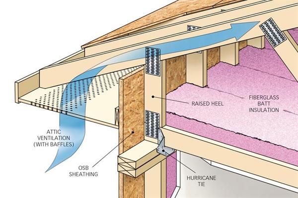
We provide buildings to clients in all 50 states, so we deal with snow loads ranging from none to over 400 psf (pounds per square foot) and design wind speeds from mild to in excess of 200 miles per hour. Along with this, clients who are blowing in attic insulation, need different heel heights depending upon thickness of insulation. In summary – there is no ‘standard’ truss when it comes to us.

I did learn a few things in architecture school. Work from inside out – do not try to fit your wants and needs within a pre-ordained box just because someone said using a “standard” size might be cheaper. Differences in dimensions from “standard” are pennies per square foot, not dollars.

Popular home spaces and sizes need to be determined: https://www.hansenpolebuildings.com/2019/09/room-in-a-barndominium/ and https://www.hansenpolebuildings.com/2019/09/the-first-tool-to-construct-your-own-barndominium/.

As far as overhangs are concerned, personally I would go without doors before I would go without overhangs. Doors can be added later, overhangs cannot. Without overhangs, buildings tend to look industrial. Overhangs afford weather protection for door openings, shade south facing windows from brutal sun, move ‘weather’ away from walls (helping to keep moisture out from under building and keeping walls cleaner), plus they afford a valuable air intake for vented attic spaces.

From a truss cost standpoint, those overhangs add very little to one’s investment.

Knee Braces in Post-Frame Buildings

Knee Braces in Post-Frame Buildings With Diaphragm-Action Design

Long time readers will recall several articles by me in regards to knee bracing, including this one: https://www.hansenpolebuildings.com/2012/01/post-frame-construction-knee-braces/

May 2023’s Frame Builder magazine (official NFBA magazine) published an article by Dimitry Reznik, P.E. and Dr. Kifle Gebremedhin specifically regarding knee braces in post-frame buildings with diaphragm action (full text can be read here: http://associationdatabase.co/NFBA/May2023/?page=16).

Here are their conclusions and recommendations:

“In the 5 buildings analyzed in this study, knee braces produced inconsistent results. Knee braces may increase or decrease horizontal eave deflection, load demand on the diaphragm, and stress unity in the posts.

Modeling knee bracing within a post-frame building is complex. The complexity extends to the roof-truss design because the truss design must include the knee brace reaction forces, The building designer is responsible for reviewing truss drawings and verify that knee brace loads are applied correctly, and that correct governing load combinations are applied while the truss designer must incorporate the load impact of the knee brace into the component design.

In all buildings with knee braces, posts were subjected to additional bending stresses under gravity loads. This behavior was more pronounced in buildings with long truss spans.

Knee braces should not be added to a building if knee braces are not specified in the design documents. Knee braces should not be specified in the design documents unless their effects on the building are considered by structural analysis.

Knee braces may benefit buildings with certain geometrical configurations and loading conditions where diaphragm action is not enough. It is recommended that the building designer first check the need for knee bracing when diaphragm action is included in the design. In the building analyzed herein, however, knee braces did not produce a consistent advantage in any of the relevant metrics of design. The stiffer frames did not consistently translate to a stronger or more efficient design. The results were mixed and highly dependent on relative stiffness of the primary frame and diaphragm.”

In layperson’s terms – knee braces should only be incorporated in fully engineered post-frame buildings where truss designs also incorporate forces imposed by said knee braces.

End Truss Overhang Dilemma

Reader ANDY in HAYDEN has an end overhang challenge. He writes:

“Hello Mr Guru. I’m building a 30x40x12 post frame with 18″ eaves. My trusses builder doesn’t build drop cord ag trusses for my gable over hangs. I was advised to lower the gable truss on the corner post to allow room for my on edge 2×8 purlinings  to extend over the top. I have a 16×10 garage door planned for below that over hang, will this method work. Can ladders be used?. I would appreciate your help sir. I know if I had the money I could have ordered one of your kits. Trust me I wish but I was born with a spork in my mouth and I’m just chipping away monthly on my project. Thank you for any help.”


Mike the Pole Barn Guru responds:

Most of our clients were not born with any sort of silver or plastic ware in their mouths – me either. While my brother and I did not realize it growing up, we were probably upper lower class in family income, but we were happy, our parents worked hard and we learned well from them. I have joked, “We were so poor our mother used to spray paint our feet black and lace up our toes”. It was not quite as bad – but Mother did go without socks for some time so we could have clothes.


Moving forward – there are advantages to investing in an engineered complete building kit package and not try to piecemeal. I have written about piecemealing before https://www.hansenpolebuildings.com/2014/03/diy-pole-building/. Ordering trusses can, as you have just found out, be far more difficult than it seems. https://www.hansenpolebuildings.com/2020/02/things-roof-truss-manufacturers-should-ask/

Financing is highly affordable, with some amazingly low interest rates and most suppliers have options available to delay some deliveries until you are more prepared for them.

Before you get carried away with an overhang, look at your engineered truss drawings. Guessing your building has a pair of trusses every 10 feet and a single truss on each end, it will need to be designed to account overhang weight plus any other dead loads and snow loads. To accomplish this, your end trusses should be designed with either one truss at five foot (plus a notation stating they can support an 18 inch end overhang), or have a spacing of 6’6″. If neither of these has occurred you need to contact your truss supplier for an engineered repair. It may be cheaper to use a double truss on one end (notching into corner and end columns, and purchase a correct new truss for the opposite end.

In any case, before there is any structural deviation from your engineered plans YOU MUST CALL YOUR ENGINEER. My suggestions are merely my opinion and are not to be construed as my supplying or practicing engineering. If you deviate from your engineered plans in any fashion, all liability for structural integrity falls directly upon you.

Measurements below are using this for a measure of eave height https://www.hansenpolebuildings.com/2015/02/eave-height-2/

Having taken care of loading issues in some fashion, you can lower your end trusses by 7-5/8″ to adjust for vertical component at a 4/12 slope (other slopes change this hold down dimension). This should put the bottom of your end trusses at 10′ 10-1/2″ for a 2×6 top chord truss (again at 4/12) or 10′ 8-3/4″ for a 2×8 top chord.

Bottom of your overhead door header should be at 10′ 5″ above grade (bottom of splash plank). This leaves 3-3/4″ only (2×8 Top chord) or 5-1/2″ with a 2×6 top chord for your overhead door header. Keep in mind, below an end truss this header carries absolutely no roof load. It exists merely to be a place for a row of screws or nails (non-steel sidings) and to be a place to attach an overhead door spring block to. If you were erecting a Hansen Pole Building, your end truss would be notched into your corner and endwall columns 1-1/2″ This allows for a 2×8 overhead door header to be installed above the top overhead door jamb and lapping onto end truss bottom chord 3-1/2″ (1-3/4″ with 2×6 top chord). Balance of end truss chords would have a 2×4 Std&btr nailed across to provide backing for siding and act as a stiffener resisting lateral loads and buckling.

Another advantage of a complete package is it should come with a detailed step-by-step assembly manual. At Hansen Pole Buildings this means 500 pages. 

Your engineer can verify if you can for 2×6 top chord truss place a 2×6 as a header between top jamb and truss, or move top jamb up 1/4″ and use a 2×4.

Ladder framing nailed or screwed to the face of end truss to create end overhangs is probably not structurally adequate and it could very well sag, if not fall off.

Best wishes.

Prefabricated Roof Trusses Part Two

Prefabricated Roof Trusses – They can Make You or Break You

In yesterday’s blog, Mike the Pole Barn Guru started to share some secrets which should both increase your bottom line as well as allow you to sleep soundly at night.

A short recap here, for the full account, read Part One posted yesterday, May 25th.

A case in point, not too many years ago, we provided the post frame building kit package for the Nature Center at the Cheyenne Mountain Zoo in Colorado Springs, Colorado. The Building Department gave the ground snow load as 27 psf (pounds per square foot), yet wanted 40 psf as the roof snow load. When our engineer called the Building Department to discuss this, the explanation given was, “The snow is just different here!”

Moving on to “the rest of the story” on prefabricated roof trusses.

Truss design programs calculate the roof snow load using Pg as the basis and multiplying it by several factors. This is the formula for the relationship between the ground snow load and the roof snow load adjusted for slope or Ps: Ps = 0.7 X Cs X Ce X Ct X I X Pg.

All of these factors should be clearly outlined on any set of plans being submitted for a structural plan check to a building department. If not, or there is some doubt, the engineer of record for the building should be consulted to make a written determination.

Cs is the sloped roof factor. Metal roofs are assumed to be slippery surfaces unless the presence of snow guards or other obstructions prevent snow from sliding. It is calculated based upon whether the roof is warm or cold, the nature of the roofing material, and the slope of the roof. With heated, steeply sloped and/or slippery roofs, these reductions can be significant.

The Exposure Factor (Ce), is most often 1.0, but can vary from 0.7 to 1.2 and can make a huge difference in both truss design and price.

The Thermal Factor (Ct) for heated buildings will be 1.0 or 1.1. However, most post frame buildings are not heated year round, and if so the factor should be 1.2.

Most truss manufacturers assume a Risk Category II (shown as “Is” or “Importance” factors on truss design drawings). Many post frame buildings will not result in the loss of human life in the event of a failure, given they are used for agriculture or storage and are Risk Category I. This alone can reduce the roof snow load by 20 percent as compared to residential, office or manufacturing type structures!

Will the building be in an area with little or no snowfall? Don’t forget area reductions. If the truss span times the truss spacing is over 200 square feet, a reduction is in order. This calculated value can reduce the roof live load (Lr) to as little as 12 psf.

Further, if Lr is greater than Ps (sloped roof snow load), the Duration of Load for roof loads is now 1.25, instead of the 1.15 typical default value.

What can you do? Make sure the values of Pg, Cs, Ce, Ct and I as shown on the plans, are provided to the truss manufacturer and are reflected on the drawings you will be asked to sign off on.

One other important thing to look for – the “fine print” on the truss drawings should state the trusses are designed for an unbalanced snow load (think drifting). Some truss manufacturers will ignore this crucial component of design, in order to reduce their truss price.

Now, let’s save you some money.

Truss bracing is important, and when neglected can result in catastrophic failures. When overdone, it can kill a building budget in materials and labor.

The truss company will produce preliminary drawings and ask you to “sign off” on them, prior to production. Look at the interior members (webs) which require lateral bracing. These are most typically longer webs which are in compression. Often bracing to web members can be reduced or eliminated by asking the truss designer to switch the direction these long webs run, which will place them in tension. Increasing the size and/or grade of the web can also help. These changes are generally less expensive than the cost of the added bracing.

Lateral bracing needs can also be reduced by using trusses which are physically doubled – installed face-to-face without blocking in between. If your standard building design is for single trusses every four feet placed on a truss carrier spanning eight feet between columns, consider going to a double truss every eight feet, which eliminates the need for truss carriers. Why would this reduce bracing? Because the double truss is now a three inch wide member, instead of 1-1/2 inches, for the most part cutting bracing needs in one-half.

Using trusses spaced over ten feet apart? The truss drawings probably show lateral bracing as a single 2x spanning from truss to truss. Any truss braces spanning over ten feet should be done as “T” or “L” braces, otherwise they can fail in weak axis bending (the skinny direction) under a load.

Learning to read and understand the information on truss drawings is crucial to the success of your business. Don’t make the assumption the truss company is going to be right. If there is something on a truss drawing which is unclear, ask the truss provider to explain it – in layperson’s terms. And, if you still have any doubts, ask your RDP.

Truss Butt Cuts

Butt Cuts, not Cracks

In a past life, when I was far younger, I was a newbie in the prefabricated metal connector plated wood truss industry. My first job was as a sawyer, I was the guy who trimmed all of the components prior to their assembly into trusses.

Although my employers had what at the time was a fairly good sized operation, technology had not yet reached us.

In today’s manufacturing process, most cutting is done on specially designed machines with as many as six blades which can precision cut lumber as long as 20 feet, as quickly as it can be fed into the saw! When I began, the saw I was trained on was a radial arm saw with a pivoting table. This allowed for only a single cut to be made at a time.

Bottom chords on triangular pitched trusses most often have a long sloped angle cut at the junction to the truss top chords. At my first job – we sawyers made a single cut, known as a feather cut. Due to slight differences in the crown of the lumber, this taper to an indeterminate point lead to some variability in assembly.

Once I had moved on to the sister plant of my first employers, I convinced the managing partner we would be producing a much improved truss, by using the industry standard “butt” or “Heel” cut at the end of each bottom chord of ¼”. The downside, it would take two cuts on the end of each bottom chord. The plus, more accurate assembly in the shop, and easier installation at the jobsite as framing contractors had an exact and consistent point to work from.

This cut also allowed the framers to position sheathing on the walls so the top edge was even with the top of the wall. The ¼” butt cut allowed the tail of the truss to clear the edge.

When I relocated to Oregon to manage the truss plant at Lucas Plywood and Lumber, I was exposed to an entirely new application of butt cuts. Most wood framed construction there was done with overhangs which were open (no soffits). 2×4 exterior stud walls were framed with a 2×6 double plate, with the extra 2” held to the outside of the wall. The siding would then be installed so it abutted the underside of the 2×6.

truss-tails
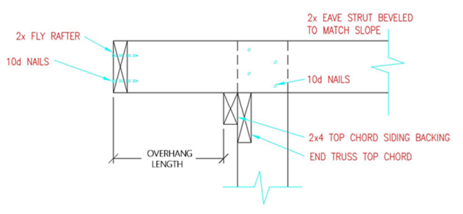
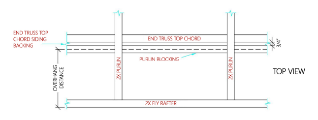
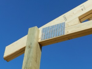
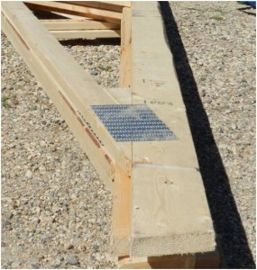
On a 30 foot wide building, the measure from outside of double plate, to outside of double plate was 30 feet and four inches. In order for the truss tails to clear the extra two inches on each wall, the butt cut was increased appropriately for the slope of the truss top chord. With a 4/12 slope, a ¾” butt cut was perfect.

Years later, my brother and I worked as truss designers for a company which built lots of trusses for pole buildings, however did not have any 2×6 lumber graded higher than 1650msr (https://www.hansenpolebuildings.com/blog/2012/12/machine-graded-lumber/).

We found we could manipulate the height of the butt cuts, gradually changing 1/16th inch at a time, to be able to eliminate overstress in truss designs by as much as 10-12%!

Dear Guru: Did I Get the Right Trusses?

Welcome to Ask the Pole Barn Guru – where you can ask questions about building topics, with answers posted on Mondays.  With many questions to answer, please be patient to watch for yours to come up on a future Monday segment.  If you want a quick answer, please be sure to answer with a “reply-able” email address.

Email all questions to: PoleBarnGuru@HansenPoleBuildings.com

DEAR POLE BARN GURU: I need to confirm that I was shipped the correct trusses for finishing out the ceiling.

On the plan drawings the ceiling joist are called out as 2×4’s on 24 inch center but are drawn with 2×6 bottom chords on the trusses.

The trusses I received are entirely manufactured with 2×4’s.  Is that correct? I know the plans state that the trusses are “Pre-fab trusses per truss manufacturer”, but do these meet the engineering design of my Hansen building and your engineering?

I read too in the plan general notes that the web design of trusses may vary from that depicted in the plans.  What I read on the truss manufacturers spec sheet I think they do but there are a lot of abbreviations and assorted alphabet soup acronyms that I don’t understand fully.

Thanks in advance, for confirming this for me. FLOUNDERING IN FINCASTLE

DEAR FLOUNDERING: The drawings for your building are done by draftspersons prior to the trusses being ordered and are merely a representation of the profile of the trusses, they are not meant to be an exact diagram of how any individual truss might actually be fabricated.

In review of the truss drawings provided by the fabricator, please note a box about 1/2 way down the page on the left side entitled “LOADING”. BCDL (bottom chord dead load) is listed as being 5 psf, which is adequate to support 5/8″ gypsum drywall, the ceiling joists and the weight of insulation.

These trusses meet the specifications of the building and properly installed should provide a sturdy roof system for generations.

Mike the Pole Barn Guru

DEAR POLE BARN GURU: Hello, I was just looking at your post from 2012 about the geothermal/radiant heating system you installed for your office there.  My wife and I are planning to renovate a barn on our property about the same size as your building and were looking to do something similar – radiant in an at-grade slab powered by geothermal.  I’d be interested in learning more about your experience with this, if you use any backup heating, how you are heating upper floors, what you do for cooling, and any other tips you might share.  We have a lot of space available for a geo field so I’d like to be able to get as much out of it as possible. IDEATING IN IOWA CITY

DEAR IDEATING: Thank you very much for reading the article. The geothermal wells are actually maybe the easiest part of the entire process and I kick myself for allowing my HVAC guy to talk me out of doing them when I remodeled my home in WA 23 years ago.

I can truthfully say I am fairly unknowledgeable when it comes to heating and cooling systems. I do know the mechanical side of our particular system is fairly unreliable, which I fault the company which did the original work, not the process itself.

On the upside – the cost to heat and cool both floors is very economical. We own a double-wide mobile home across the road from this building which we always thought was fairly reasonable, but the barn costs are about half of what it costs to heat and cool the mobile home, and it’s over 4 times larger. We love it that the floors on the lower level are always somewhat warm.

We do use electric forced air to handle the air in the upper floors.

For real expert advice, I’d suggest contacting www.radiantoutfitters.com

Mike the Pole Barn Guru

DEAR POLE BARN GURU: Hello,

I’m looking to install a Sliding Steel Door to fit an opening of 10 ft high by 12 ft wide onto my Man Cave.

The building is sided in grey vinyl.   What color options are available?

We get winter snow so would January operation of the door be affected??  Does it have bottom rollers or simply hang from the top?

Are these doors secure from vandals??

Thank you. LOREN IN LORAIN

DEAR LOREN: There are going to be some good things and bad things about sliding doors. Most people think of sliding doors as the first option, in the belief they will be significantly less expensive. In most cases, this is just not the case.

GOOD:

They can be sided with any possible material – including gray vinyl. Least expensive and most durable will be steel siding which is available in a wide variety of colors.

NOT AS GOOD:

They are not airtight – go with the assumption your neighbor’s cat will be able to enter your building.
They are not practical to insulate.
While they do have trolleys which hang from an overhead track, there is also a bottom guide attached to the base of the wall in the direction the door slides.
In all probability, in snow country, the door will probably get frozen in one position.
Generally I would not consider them as being secure from vandals – they will keep the honest people honest.
Electric openers are far more costly than standard openers.

In all probability your best option will be a sectional overhead door.

Mike the Pole Barn Guru

Pole Building Truss Framing

My Truss Framing Does Not Match the Plans

Every good set of pole building plans should have at least one page upon which is drawn a “cut through” view or cross section of the building. To read about what should be depicted on this page: https://www.hansenpolebuildings.com/blog/2011/10/pole-building-plans-101-interior-section-elevation/ or actually view an example at: https://www.hansenpolebuildings.com/sample-plans.htm.

sample building plans
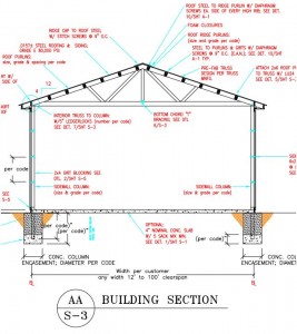
One of the features of this page, for buildings utilizing prefabricated roof trusses, is a generic representation of the roof trusses. The trusses will be shown accurately for span (the length of the truss from outside of column to outside of column) as well as roof slope. Any lateral (the length direction of the building – perpendicular to the trusses) permanent bracing for the truss top chords (the roof purlins) as well as the bottom chords which are required by the Engineer of Record, will also be depicted on this drawing.

As the person doing the drafting is not privy to the final trusses drawings, provided by the roof truss fabricator, at the time the plans are drawn, truss members on the plans will not resemble those of the actual delivered trusses.

What things might be different? Everything!

The sizes of any and all members could very well be different than drawn. As well, the configuration (or pattern) of interior truss members (webs) will most likely not even be close.

Do not fret – they are not meant to be a match.

An often confusing part of the sealed truss drawings from the manufacturer, may be what is shown as top chord bracing. Many times what appears on the drawings as a 2×4 placed flat over the top of the truss, is merely the truss engineer’s showing the recommendation for the truss to be braced. The Engineer of Record is responsible for permanent truss bracing design, which is typically accomplished by the roof purlins being placed on edge between the trusses.

Breathe deep, exhale completely and move forward following the truss framing installation instructions, and everything will be just fine!

Open Web Wood Floor Trusses

Most of us don’t think too much about the floors we walk upon – unless they are not level, squeak when we walk on them, or are too bouncy.

open web trussesTraditionally wood floors have been framed with dimensional lumber (2×6, 2×8, etc.), usually spaced 16 inches on center. Often floor joist span limitations are not based upon the strength of the lumber (the ability to carry a load), but upon deflection criteria. Building codes limit floor deflection to L/360, where “L” is the length of the span, in inches.

The “stiffest” (by MOE – Modulus of Elasticity values) commonly used framing lumber is Douglas Fir. A #2 grade Douglas-Fir 2×12, 16 inches on center will span 18’1” when carrying standard residential loads. An L/360 deflection event, would cause the center of one of these floor joists to deflect as much as 6/10ths of an inch!

Lumber is organic, so it varies in consistency from one board to the next. It also varies in size, and it is not unusual for a dimensional variance of over ¼ inch, from one end of a board to another. Combine this with the probability some of the boards will be crowned the wrong way, and it means an uneven floor will result.

One of our friends lives in a fairly new home. In the hallway between her kitchen and the sleeping areas, there is a good ½ inch dip in the floor – more than noticeable when walking across it!

I first used floor trusses in my own pole building almost 20 years ago. My trusses were designed so they were only 1-1/2” thick, but the 30 foot span trusses are only 24 inches in depth. They allowed me to create some unique interior areas, without the need for columns inside the building.

When we built our home in South Dakota, we utilized floor trusses again – here to span 48’ (yes 48 feet)! We live upstairs in a gambrel building, with a clearspan ½ court basketball court size garage downstairs!

A few years ago, my oldest son Jake needed a new garage – his mom convinced him the design would be so much better with a mother-in-law apartment upstairs. We used 4×2 (2x4s turned flat) floor trusses to span the 24 foot width!

I’d forgotten how fast a trussed floor can be done – until Jake used them for the support of the second floor in the addition he is now putting on his home. In a matter of just a couple of hours, the entire 24 by 32 floor was framed and ready for sheathing. All of the ductwork can be run through the open truss webs, making for nice clean ceilings downstairs.

Considering a second floor loft in a pole building? Don’t want posts down below to get in the way of full space utilization? Then floor trusses may be the answer.

Make sure to allow adequate height for the thickness of the trusses. As a rough rule-of-thumb, I plan upon one inch of thickness, for every foot of span. While it will nearly always be less, it is better to design for having a couple of extra inches, than not enough.

Dear Guru: Altering Roof Trusses

DEAR POLE BARN GURU:Currently constructing building and the roof trusses are not built according to engineered plans. Plans call for 2*10 and these trusses are 2*6. Builder has purchased additional materials to reinforce the trusses.

Now the steel is going up today and found that the 2 11’10” clay endwall pieces are missing. Builder also informed me that there are not any gutter endcaps. SPINY IN SOUTH DAKOTA

DEAR SPINY: Thank you very much for investing in a new Hansen Pole Building kit package last year.

Roof trusses on building plans are typically just an approximation of what the trusses may look like, as the draftsperson does not have the drawings from the roof truss manufacturer when plans are produced. In reviewing the engineer sealed truss drawings from the truss company, indeed 2×6 trusses will carry the loads appropriate for your building.

Either you, or your builder, really should have been in contact with us prior to your trusses being altered. Even though “reinforcing” the trusses may have seemed like a good idea at the time, it is very possible their ability to properly carry the loads has been compromised. A prefabricated truss should never be altered, without the approval of the manufacturer and their engineer.

Weird things do happen from time-to-time, and your steel order happens to be one of those. Our Material Takeoff (which was provided to you last year so you could do inventory) does happen to show the 11’10” pieces, as does our order to the steel company. For whatever reason, the steel company did not process these two pieces and they do not appear on the return paperwork from the manufacturer.

We do provide explicit instructions as to inventorying all materials as they are received by you. You are given 48 hours after receipt to notify us of shortages – for many reasons. Suppliers are paid by us, based upon the Purchase Orders we place, so we have had to pay for the two panels which you did not receive. We also want to prevent construction delays. If we had known these panels were not received by you 10 months ago, with the rest of your order, it could easily have been rectified then.

Even though the missing panels were not reported as expected, we will be providing them to you at no charge.

On the gutter endcaps – we did not provide your gutters, you may want to contact whomever you contacted to provide the gutters

Dear Guru: Can My Pole Barn Trusses Handle a Ceiling Load?

DEAR POLE BARN GURU: I have a question regarding truss loads, specifically ceiling loads, for a pole barn.  I know you have touched on this before, but I was hoping for a little more detail.

I recently purchased a property that came with an existing pole barn, and other than a few material ratings I cannot find any data on the trusses (no manufacturer tags, etc).  The building is 32×48, and the trusses 4/12 pitch with 2×6 top cord, and 2×4 bottom cord and webbing, on 4′ centers.  I want to add a steel ceiling, plus insulation and lighting. By my math I am looking at a dead load of 2-3 lb/sq ft, including the weight of the bottom cord of the trusses.

I have done a lot of research on the subject, and it seems that it is common in pole buildings to have trusses spaced much wider than 4′ (8’+ seems common).  Is the tighter spacing a indication that these trusses should support a 2-3 lb/sq ft dead load for ceiling and insulation?  If you were specing trusses for my requirements, how would you design them?  If these trusses are not sufficient, what sort of reinforcement would be required?

One of the only bits of data I have been able to find is this page https://www.pole-barn.info/gable-roof-trusses.html, where toward the bottom it lists a 30′ span with the same lumber sizes as my trusses.  While it says “no ceiling” it also lists a bottom cord dead load of 5 lb/sq ft, which would be plenty for what I have planned. BAFFLED IN BOZEMAN

DEAR BAFFLED: The spacing of the roof trusses has no influence upon their load carrying capacity. In reality, trusses spaced 12 feet on center could easily have a greater ceiling load carrying capacity than ones placed even every two feet!

As a starting point, you should assume the trusses are NOT designed to support dead load weight of anything other than the trusses themselves, required bracing and minimal wiring and lighting.

The size and or grade of the truss chords as well as the webs and their quantity, and the size of the roof truss plates may not be adequate to carry the weight of the ceiling load. It’s not as easy as just knowing the size or spacing of each part, but rather it’s more of how all the parts function together in any configuration.  In other words, it’s a formula with many parts which change the final answer of “yes” or “no”.

The only safe way to make sure your new ceiling doesn’t end up on the floor with the rest of the roof following it, would be to hire an engineer to confirm the trusses are adequate to support the ceiling load, and to design a repair for them, if necessary.

DEAR POLE BARN GURU: We are builders, putting up a Hansen Pole Building currently. It is large enough so the main clearspan building and attached shed had to be shown on two different pages of the blueprints. Anyhow, we made a mistake on setting the poles. Where we are looking at the 4 posts going across up by the “matchline”  we have the left sidewall posts set correctly but the 2 main building posts and the right side shed post are set incorrectly. We ran a string line but the workers ended up setting those 3 posts on the other side of the string line.

I am wondering if there is an easier solution than pulling out the posts. We have a lot of concrete in the holes and it would be hard to get them out. Could we fir out the left sidewall posts and go out and buy longer purlins? ERRANT

DEAR ERRANT: While this doesn’t happen often, you are not the only person to have this problem. In this particular case, you are constructing an engineer certified post frame building, which means any deviation from the plans is going to have to be approved by the engineer. This is going to mean time delays and the expense of paying the engineer.

Even if it was not an engineered building, using purlins for a span which is now 5-1/2 inches greater could overstress the purlins in bending. While 5-1/2 inches may not sound like much, in the design calculations for the purlins, the span is squared.

I’ve had to pull out concreted in columns before, and it isn’t fun. Best method I found was to use a backhoe or loader, wrap a chain around the column and lift it out. Fairly fresh concrete can be chipped away from the column and the process of setting the three columns can begin again.

I’m sorry I don’t have an easier solution, but you will be much happier with the outcome if you do reset the posts. And all in all, it may end up being far less expensive as well, in both time and materials.  As I said, I’ve done this myself, so I am right there with you.  The good news is, once you reset the posts, just knowing you have things all “in order” will make the project run smoothly from here on out


Overhead Crane

OK, I was web surfing again! My wife thinks I spend all of my time on the ‘net Facebooking….well, I actually do some real research.

I found this post recently on www.garagejournal.com, in reference to a comparison between all steel and post frame (pole) buildings. The poster cited this as why he regrets not having constructed an all steel building for himself:

The down side for me was not being able to spec the building with an overhead crane supported by the trusses. If I went with steel I’d have a five ton overhead in my shop right now. I really regret that”.

Hoist Mounted To Wood TrussesShaking the dust off from my prefabricated wood roof truss designer’s hat (I have owned my own truss plants from another life), I can assure the writer he was sadly misinformed. There were numerous times I designed a roof truss system to support suspended crane loads.

Take this example, a 50 foot span pole building, with doubled (two ply) trusses spaced every 12 feet. Adding a five ton load to these trusses would be the equivalent of under 17 psf (pounds per square foot) of load being added. Highly doable. The truss designer would need to know where on the trusses the load would be supported, and then they can be designed accordingly. With very wide spans, or high loads, increasing to a three ply truss, from a double, may be required.

More often than not, overhead crane systems in pole buildings are supported from the wall columns. The columns are very strong in compression (downward load) and the connection of a crane system to the columns can be done relatively easily. The cautions would be to make sure the system (both building and crane attachments) are designed by a RDP (Registered Design Professional – an architect or engineer) and the column footing diameters are increased appropriately to account for the added weight of the system.

With truly informed experts on the design side of the equation, almost anything can be done with a pole building, and usually at a more reasonable cost than other alternatives.

High Performance Pole Buildings & Insulation

Pole Buildings and Insulation

When designing a high-performance pole building – whether it be residential or commercial, the heating and cooling loads need to be shaved everywhere they can be. Thermal bridging creates hot spots or cold spots in the building envelope, and this makes a difference for heating and cooling costs—as well as for comfort.

One example: the juncture where walls intersect roofs. If a design calls for 16 inches of fiberglass insulation in an attic, but overall height at the end of the roof truss is only six inches (which would be fairly typical of a 2×6 truss top chord), there’s no room for this amount of insulation at the eave edges of the building. Millions of buildings which have code-compliant attic insulation over most of the ceiling area have compressed insulation all around the house perimeter—which means the owners haven’t gotten the most out of their insulation.

energy heel truss - attic insulation

Credit: Harry Whitver

Fortunately, truss manufacturers know how to build raised heel trusses (also called energy trusses) which leave room for full-height insulation all the way across the joint where the trusses attach to the sidewall columns.

Typically, the tall heel of the truss sits flush with the outside of the sidewall posts, creating a continuous plane which can be sided over. Where the trusses are directly notched into the sidewall columns, and properly attached, the extra bracing which would otherwise be required in conventional stick frame construction can be avoided.

A properly qualified and well experienced post frame building supplier knows how to engineer the bracing and connection details to meet local codes and national design standards.

The relatively small cost to properly design and build a pole building to be the most energy efficient, as well as practical, is small – compared to the cost to unnecessarily heat or cool outside of the building envelope itself.

What is a Truss?

Having grown up the son of a framing contractor, then working framing for my father and uncles as a teen, I take for granted everyone knows what trusses are. When my first daughter, Annie, was just a wee tyke, she used to fold napkins into triangles – she told me she was, “building trusses”, like her dad who was then working at a prefabricated roof truss plant.

Look around you – Look up, down and out the window. Do you see a series of triangles? Did you look up at the series of triangles? Did you look up at the roof, down at the floor or out the window at a building or bridge? Whether or not you can see the triangles, the structures around you likely contain a truss. In the most basic terms, a truss is a structure composed of one or more triangles. Why a triangle? Well, think about a triangle’s geometric shape – it’s so simple, yet its shape and design are structurally stable.

A technical definition of a truss is, “A rigid framework composed of members connected at joints and arranged into a network of triangles.”

Trusses are made from various materials, including the most popular: wood or light and heavy gauge steel. Trusses come in two and three-dimensions and the triangles are connected with various types of materials such as metal plates for wood trusses or screws for steel trusses. One of the most famous structures in the world, the Eiffel Tower, is a truss – a series of inter-connected triangles. Trusses are also used to construct bridges, roofs, floors and even the Statue of Liberty.

The modern wood roof truss was invented by Carroll Sanford in 1952 at Pompano Beach, Florida. While playing around with plywood gusset plates, glue, staples, nails and screws, Sanford stumbled upon the idea for the first metal plate-connected wood truss and he patented the system.

In the late 1950’s and early 1960’s, pre-fabricated roof trusses were introduced. One common brand was Gang-Nail (now Mitek). These trusses used a multi-nail plate connector and companies could quickly and cheaply mass-produce them.

Today, roof trusses allow for large spans between walls. This allows buildings to have more open designs. You can also create a “box” within the triangle of a truss, so an upper area of a building can have a boxed out “clear” area for a room.  These are called “attic trusses”.  Trusses, (still triangles) can also be designed so the bottom cord ends up with a triangular design to it.  Ceilings below them can then have a vaulted ceiling look.  Just a slight change like this can alter the entire look and “feel” of the inside of a room. Wood trusses are used in every kind of building, from “stick built” residential homes to pole building construction. Simple in design and yet (excusing the pun), they are built… to carry a lot of weight!

Pole Barn Truss Spacing

What do you mean they are not 2 feet apart?

Back in the day (early 1990’s) I was on the National Frame Builders Association (NFBA) Board of Directors. One of my fellow board members from the Midwest wanted to take a peek at how pole barns were constructed in the West, so I invited him out for a tour.

After spending a day looking at several of our building projects, his comment to me was, “The inspectors in our area would never let a pole building be constructed with roof trusses placed every 12 feet”.

Twenty years later, I beg to differ. Hansen Buildings has buildings in each of the 50 states and all of them have roof trusses on what my board member friend would describe as being “widely spaced”.

Modern truss design is highly computerized. Enter the span of the truss, bay spacing and load conditions and the engineering programs will design a truss which will meet the design criteria. The lumber and steel plates the trusses are constructed from, have no idea how far apart they are going to be placed.  They are inanimate! Yet, somewhere in the deep, dark reaches of history, lies the theory wood trusses must be spaced no more than 24” on center, or maybe 48”, or perhaps even eight or ten feet? The reality is, there is no magic number.

Framed Pole Barn

36′ long garage with 12′ bays

While D. Howard Doane is credited with being the innovator of the modern pole barn, it was his Agricultural Service farm manager, Bernon Perkins, who is credited with refining the evolution of the modern pole building to a long-lasting structure.  It was Perkins who pioneered roof purlins being placed on edge. With this design change, roof trusses could be placed 12 feet apart, making it possible for roofs to support the loads to which they would be subjected.

I’ve had roof truss manufacturers try to convince me it is impossible to place wood trusses at spacings of over every 4 feet. Their defense is, “Our engineers will not allow us to”. The manufacturers of the steel roof truss plates (also referred to as gussets or Gang-nails), provide the engineering design for pre-fabricated wood trusses. Their programs will allow for trusses to be placed on 12 foot or even 16 foot centers, and their engineers will place their engineer’s seal on the drawings to verify.

The practicality, cost effectiveness and ease of construction of pole buildings is based upon efficient use of the fewest amount of materials, to do the most work, within safe engineering design. Hundreds of thousands of pole barns are in use today with trusses spaced every 12 feet, or even more. They stand as a tribute to the ingenuity of modern pole building design.