Tag Archives: splash plank

How to Frame an Overhead Door Opening

How to Frame an Overhead Door Opening

Reader DAVID in SPURGEON asks:

“How to frame in an opening for a 10 foot by 10 foot overhead door?”

This except from Hansen Pole Buildings’ Construction Manual should get you going:

Chapter 24: Overhead Door Openings

Most Common Mistakes:

  1. Column(s) next to door turned the wrong direction.
  2. Header placed at incorrect height.
  3. Wall out of square prior to framing opening.
  4. Door opening bottom at other than 3-1/2” above bottom of splash plank.
  5. Failure to install
    A ears in residential door applications.
  6. Vertical Jamb bottoms set other than at 4” above bottom of splash plank.

Overhead door columnsUsually 4×6 pressure treated, if required, will typically be oriented 6” toward wind, unless wall columns are 6×6 or larger.  Correct orientation will be shown on building plans. Space between columns, for residential doors, will be approximately door width plus 1”. For commercial (ribbed) doors space between columns will be approximately door width plus 3”.

Overhead door openings are planned so as to allow an approximate 1” overlap where overhead door panels and jambs meet. This helps to minimize possible weather infiltration.

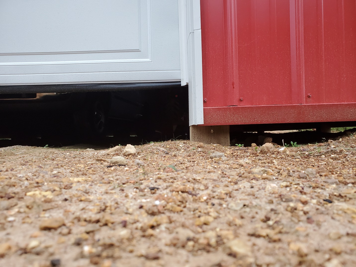
What if no concrete slab on grade is planned for? Chances are good, as some future date, someone will add a concrete slab. Door bottom should always be placed at 3-1/2” above splash plank bottom. Build a gravel (or similar material) berm across the opening, up to the bottom of the door (again 3-1/2” above splash plank bottom) in order to provide a seal easily removable if and when a concrete slab on grade is poured.

With wall columns 6×8 or 2×8 glulams (or larger), it is possible a 2×4 filler (or fillers) will need to be added to the inside face of a smaller dimension column on one or both sides of overhead door openings. This will be indicated on plans with language like “4×6 SYP #2 W/ 2×4 STD FILLER ON INSIDE FACE”. This filler should be installed on the inside face of the column in question, with bottom of filler 1” above top of concrete slab, vertical edge tight to overhead door jamb and top at height of header. Attach with 2-10d common nails 12” on center.

As overhead door columns have been set from dimensions called out for on building plans, only requirement is to create a “picture frame” to place the overhead door behind.

Vertical jambs will be cut from pressure preservative treated lumber and installed first. If a choice is available, use straightest possible boards for these. 

If overhead door opening columns are 6×4 (with 6-inch face towards wind) jambs will be 2×6 (with sidings other than steel or vinyl 2×8). 

If overhead door opening columns are 4×6 (with 4-inch face towards wind), 6×6 or 3-ply 2×6 glu-laminated, jambs will be 2×8 (with sidings other than steel or vinyl 2×10).

If overhead door opening columns are 4×6 with a 2×4 Std. interior filler, 4×8, 6×8 or 3-ply 2×8 glu-laminated, jambs will be 2×10 (with sidings other than steel or vinyl 2×12).  

In steel or vinyl sided applications, jambs may be multiple members (e.g. two 2×4 or a 2×6 plus a ripped 2×4, rather than a 2×8), as they cover with steel trim.

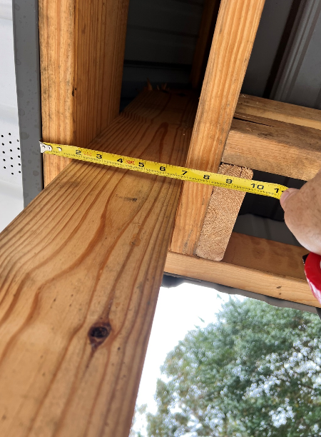
Cut vertical jambs to length first. They will be 1-1/2 inch less in length than residential overhead door vertical height (e.g. 9’10-1/2” long for a 10’ tall door), ½ inch less for commercial doors. When installed, vertical jamb bottom edge will begin 4 inches above splash plank bottom. Install with cut end up.  See Figure 24-1


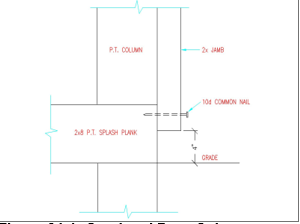
Figure 24-1: Overhead Door Column

Hold vertical jamb in place with any “crown” out and vertical jamb edge top and bottom

 1-1/2” outside column edge. See Figure 24-2


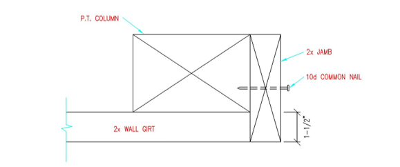
*For vinyl siding hold vertical jamb 1-15/16” outside column edge. For other (non-steel) sidings, hold inside jamb edges flush with column inside faces or inside face of commercial bookshelf girts.
Figure 24-2: Vertical Overhead Door Jamb – Plan View

Tack into place with one 10d common nail at each jamb top and bottom.

  Important:  Do NOT drive door jamb nails in completely yet!

Place shims between vertical jambs and overhead door columns so jambs are plumb in both directions. For installation when overhead door column(s) are wet set bracket mounted, use shims thick enough to avoid having to notch into vertical jambs to accommodate bracket and bolt heads.

Ideally, space between vertical jambs for residential doors is approximately equal to overhead door width, less 2”. Commercial doors space is equal to door width.

For example:  For a 10’ width residential door, space between jambs will be about 9’10”. If this varies slightly, rest assured, doors will still seal.

OK, now nail jambs securely into place! 

Cut horizontal jamb to length: at width between jambs plus 3”. Place horizontal jamb flat, on vertical jamb tops, flush with vertical jamb outside edges and with any crown out. Nail downward through horizontal jamb ends into vertical jamb top butt ends to secure in place.

Dog Ears

Dog ears are only used on residential overhead door openings. Dog ears are for appearance only and, while not recommended, may be omitted.

From lumber cutoffs, cut two 17” long “dog ears” for each overhead door opening. It is possible to get three dog ears from one board 48” in length. See Figure 24-3


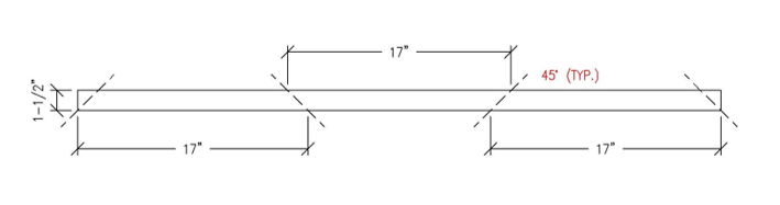
Figure 24-3: Cutting Dog Ears

If windows are to be in overhead door top section, dog ears can be cut slightly shorter to prevent window trim from rubbing as door is raised and lowered.

Install dog ears in framed opening upper corners. See Figure 24-4


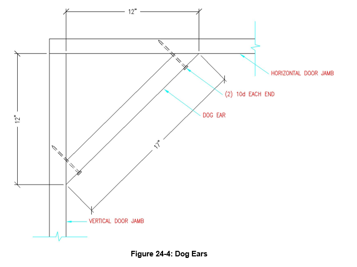
Figure 24-4: Dog Ears


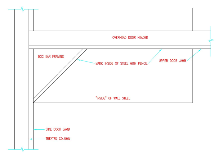
Figure 24-5: Dog Ears – View From Inside Building

Overhead Door Header

For doors 12’ and less in width, install 2×6 overhead door header, above horizontal jamb, with “crown” up. Doors over 12’ wide, header will be 2×8. Header extends to at least column middles on each side of opening.

There is only a header on column outside faces.  See Figure 24-6


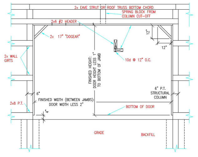
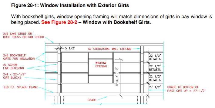
Figure 24-6: Exterior Girts Residential Overhead Door Installation

Nail upward, through horizontal overhead door jamb, into door header bottom 1-1/2” edge with 10d common nails, 12” o.c.

Using a cutoff piece from a building column, install a spring block at header center on horizontal jamb top. PLEASE NOTE: There will be no spring block for coil door applications.

Replacing Panels, Rebar in Column, and Wholesale Purchases(?)

This Wednesday the Pole Barn Guru answers reader questions about replacing old steel panels and adding an overhead garage door, if rebar is needed in the column to collar connection of the footing, and the ability to buy rock wool insulation wholesale.

DEAR POLE BARN GURU: I’m purchasing a small farm in rural Missouri. It has a 24′ x 60′ pole barn. the framing / structure is in good shape. It has corrugated metal panels. these are sound, but the looks are poor. It also has the sliding barn type door. My hope is to re-face the building with better looking panels and put in an overhead-style door ( garage type door). JOHN in NEWINGTON

DEAR JOHN: New steel cladding would certainly “freshen up” looks of this building. It would also allow for steel siding to be held up from grade (by adding a pressure preservative treated splash plank at base), rather than being run into ground.


DEAR POLE BARN GURU: Does rebar need to be installed in the concrete that surrounds the column in a pole barn? I will have holes of 12″, 18″ and 24″. Thanks. LOUIS in STEPHENS CITY

DEAR LOUIS: Unless it is called out for on your engineer sealed plans, there would usually be no requirement for rebar in concrete column encasement.

A 12″ diameter hole would be very unusual as Codes require a 4″ minimum space between corners of columns and edge of holes (a 4×4 perfectly placed in the center of a 13″ hole would meet Code requirements).


DEAR POLE BARN GURU: Hi, I was watching a video on Youtube recently and saw a guy hanging 6″ rock wool batt insulation. I was wondering if you might know where I can buy this product wholesale? I built a 30×64 and am at that stage where I’ll be looking to insulate myself soon. MARK in ARAPAHOE

DEAR MARK: Unless you are willing to buy an entire 53′ van box of rock wool, you are not going to be able to purchase it wholesale and even then you would need to provide proof you would be distributing on a regular basis from an established business in construction supply trades.


Full Frost Foundation?

Full Frost Wall Foundation?

Reader AARON in ROSEVILLE writes:

Assuming (not yet verified) that I don’t need a full frost wall foundation for my barndo, wondering about the pros/cons for full frost wall vs pier footings in southern MN. Obviously there is the cost difference, but when it comes to building performance(in the winter), would you recommend frost wall over pier footings? And are there any work arounds to improve the cold weather performance of a pier footing?”

Mike the Pole Barn Guru responds:
When we built our post frame barndominium in NE South Dakota 16 years ago, we could have utilized any foundation type we wanted. We opted for embedded columns and have had absolutely no regrets about our choice.

From a standpoint of both Code requirements, as well as performance over time, there is not a structural reason to use a full frost wall for a post frame barndominium.

Any heated structure should be meeting the most recent edition of ICC’s (International Code Council) 2021 IECC (International Energy Conservation Code), even if not required in your jurisdiction (usually due to either no structural permit requirements or not yet adopted).  You can look up your county’s Climate Zone at: www.codes.iccsafe.org/content/IECC2021P2/chapter-3-re-general-requirements. Once you know your Climate Zone, Chapter 4 will guide you through insulation requirements for roofs/attics, walls and floors.


In Minnesota, Code requires slab edges to be insulated down four feet with R-10 insulation. With post frame construction, you can rip 4′ x 8′ sheets of R-10 EPS in half lengthwise. Attach lengthwise to the inside of pressure preservative treated splash plank (aka skirt board or bottom girt) with top of insulation even with eventual top of concrete slab. Balance of requirement is solved by using another two foot piece horizontally at the bottom of vertical insulation (basically forming an insulation “L”). This does require digging a trench, however one would need to be dug (and far deeper) for a concrete foundation wall.

Now your challenge….how to insulate piers. Whether using embedded columns with a concrete footing/bottom collar, or full concrete piers with wet set brackets, you can build square forms out of EPS. It does mean you will have excess insulation on the under slab side of the pier, but it is a viable and cost effective solution.

Best way to ensure a successful outcome is with really great site preparation. If you would kindly visit our website www.HansenPoleBuildings.com and navigate to SEARCH in the upper right corner. Type in SITE PREP and hit ENTER. Up will come a plethora of relevant articles for your reading pleasure.

Calculate the Basic Stats

Calculate The Basic Stats:
by Mike Momb, Technical Director, Hansen Pole Buildings, LLC

Basic Stats for Post-Frame
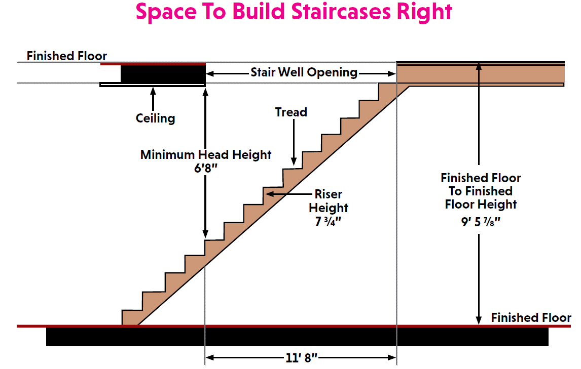
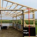
Home Floor Plans
If there is a single commonality among us humans, it is this – we are dimensionally challenged. This situation is even more so crucial when it comes to planning your new post-frame home.


Here are a few tips to help you when you are
planning it out with your builder:

Eave Height
Speak the same language as your builder. Eave height and
ceiling height are different. Your builder will likely measure

from pressure-treated splash plank bottom, to the intersection roofing underside at sidewall columns. This is not to be confused with ceiling height (also known as interior clear height).

How To Get An Eight-Foot Finished Ceiling
A ceiling of proper height is also critically important in
your home, as are door thresholds. There are many things your builder will take into account to bring that 8-foot finished ceiling into reality.

For discussion’s sake (and as most post-frame homes are
concrete slab on grade), it is likely that your builder will set a
“zero point” at exterior grade (pressure treated splash plank
bottom), the slab top will be at +3.5″.

To create eight-foot finished ceilings requires 8’1-1/8″ (al-
lows for 5/8″ sheetrock on ceilings). This puts us at 8’4-5/8″.

Now allow for roof system thickness. With recessed roof
purlins, 6-1/16″ for truss heel height with 2×6 top chord at
4/12 slope (provided you are using closed cell spray foam
insulation between purlins). Minimum eave height would
then be 8’10-11/16″.
If using blown-in insulation truss heel height should be
insulation R value divided by 3 plus 2″ to allow plenty of eave
to ridge air flow above insulation.
The builder will take care of the technical differentials mentioned above. The important thing for you, the consumer, to make sure you end up with in the end is a high-enough ceiling that provides proper venting function for the home and roof.

What about two floors?
A post-frame home can be designed to include area that
have two-floors. In order to be able to run utilities (e.g.
plumbing and duct work) through second floor supports, I
highly recommend 4″ x 2″ prefabricated wood floor trusses.
Generally truss depth will be about an inch for every clear
span foot with a 12-inch minimum. Adding an arbitrarily
chosen 16″ deep floor truss and 8′ ceiling on second floor to
example in previous paragraph puts eave height at 18’4-9/16″.

Appropriately Size Spaces
Below are popular post frame home rooms and
their average square footage, in three categories
(listed as small/medium/large):
• Entry Foyer (65/89/138)
• Kitchen (193/275/423)
• Walk-In Kitchen Pantry (17/31/51)
• Great Room (487/481/680)
• Dining (148/196/281)
• Living (256/319/393)
• Family (311/355/503)
• Recreation (216/384/540)
• Entertainment/Media (140/192/280)
• Master Bedroom (231/271/411)
• Master Bathroom (115/144/210)
• Secondary Bedrooms (130/139/178)
• Other Bathrooms (93/146/313)
• Laundry (67/87/145)
• Utility/Mud Room (30/48/80)
Always allow adequate space for hallways
(same minimum width rules apply as stairs).

98 Pro Tips On: Your Post-Frame Home
4-Foot Stairs?
Stairs are an important to function well in a home. It must
be said that stairs challenge even many experienced builders.
Finished width must be no less than three feet (if planning
allows, four feet is so much nicer), and allow for drywall on
each side when determining interior framing of stair opening
width.
In most jurisdictions maximum tread rise is 7-3/4″ and
minimum run is 10″. In above example, second floor top is
9’5-7/8″, so stairs would need at least 14 treads, taking up
at least 140″ (11’8″) horizontally. At stair top and bottom a space, in travel direction, equal to stair width must be provided. Headroom along every point of finished stairs must be no less than 6’8″. This will allow most people the ability to not hit their head and allow for them to carry items comfortably
on the stairs. A little width makes moving furniture up and down between floors a bit easier.

Allow For Wall Thickness

Different providers measure their building footprints differently – some use wall girt outside at ‘call out’ while others use column outside and are three inches greater in width and length, this will need to be accounted for in room dimensions.

Make sure you understand how the wall thickness required
for insulation impacts your room design options.
Exterior walls with bookshelf girts will be wall column
thickness plus 1-1/2″ for girts protruding outside of columns.
With 3 or 4 ply 2×6 glulams or 6×6 columns allow 7-1/4”
plus interior sheetrock thickness. Interior 2×4 walls with 1/2″
sheetrock on each side end up 4-1/2” thick.
There are many options that impact how your wanted design will fit in with your home size. Being able to understand the factors that may impact your liveable space is likely to help you end up with a great staircase and ceiling high enough to avoid some unwanted headaches.

Space To Build Staircases Right

Ceiling

Stair Well Opening

Finished Floor

Coming Soon! Pro Tips On: Your Post-Frame Home


Basic Stats for Post Frame Home Floor Plans

Basic Stats for Post Frame Home Floor Plans

If there is a single commonality among us humans it is this – we are dimensionally challenged. This situation is even more so crucial when it comes to planning your new post frame home.

Here are a few tips to help you out:

EAVE HEIGHT

Measure from the pressure treated splash plank bottom, to intersection roofing underside at sidewall columns. This is not to be confused with ceiling height (also known as interior clear height).

HOW TO GET AN EIGHT FOOT FINISHED CEILING

For discussion’s sake (and as most post frame homes are concrete slab on grade), set a “zero point” at exterior grade (pressure treated splash plank bottom), slab top will be at +3.5 inches.

To create eight foot finished ceilings requires 8’ 1-1/8” (allows for 5/8” sheetrock on ceilings). This puts us at 8’ 4-5/8”.

Now allow for roof system thickness. With recessed (joist hung between trusses) roof purlins, 6-1/16″ for truss heel height with 2×6 top chord at 4/12 slope (provided you are using closed cell spray foam insulation between purlins).  Minimum eave height would then be 8’ 10-11/16”. If using blown-in insulation truss heel height should be insulation R value divided by 3 plus 2″ to allow plenty of eave to ridge air flow above insulation.

What about two floors?

In order to be able to run utilities (e.g. plumbing and ductwork) through second floor supports, I highly recommend 4” x 2” prefabricated wood floor trusses. Generally truss depth will be about an inch for every clear span foot with a 12 inch minimum.  Adding an arbitrarily chosen 16” deep floor truss and 8’ ceiling on second floor to example in previous paragraph puts eave height at 18’ 4-9/16”.

Stairs challenge even many experienced builders. Finished width must be no less than three feet (if planning allows, four feet is so much nicer), allow for drywall on each side when determining interior framing of stair opening width. In most jurisdictions maximum tread rise is 7-3/4” and minimum run is 10”. In above example, second floor top is 9’ 5-7/8”, so stairs would need at least 14 treads, taking up at least 140” (11’ 8”) horizontally. At stair top and bottom a space, in travel direction, equal to stair width must be provided. Headroom along every point of finished stairs must be no less than 6’8”.

ALLOW FOR WALL THICKNESS

Different providers measure their building footprints differently – some use wall girt outside at ‘call out’ while others use column outside and are three inches greater in width and length, this will need to be accounted for in room dimensions.

Exterior walls with bookshelf girts will be wall column thickness plus 1-1/2” for girts protruding outside of columns. With 3 or 4 ply 2×6 glulams or 6×6 columns allow 7-1/4” plus interior sheetrock thickness. Interior 2×4 walls with ½” sheetrock on each side end up 4-1/2” thick.

APPROPRIATELY SIZE SPACES

Below are popular post frame home rooms and their average square footage, in three categories (listed as small/medium/large):

Entry Foyer (65/89/138)
Kitchen (193/275/423)
Walk-In Kitchen Pantry (17/31/51)
Great Room (487/481/680)
Dining (148/196/281)
Living (256/319/393)
Family (311/355/503)
Recreation (216/384/540)
Entertainment/Media (140/192/280)
Master Bedroom (231/271/411)
Master Bathroom (115/144/210)
Secondary Bedrooms (130/139/178)
Other Bathrooms (93/146/313)
Laundry (67/87/145)
Utility/Mud Room (30/48/80)

Always allow adequate space for hallways (same minimum width rules apply as stairs).

Questions from a Future Barndominium Owner

Reader JASON in WINDSOR writes:

“What are ways to avoid a stone base for slab to protrude under grade board using a post in the ground or pier with wet set brackets? We want grass to grow right up to the building’s base rather than stone around the perimeter or stone flower beds. I don’t like the idea of moist soil on treated grade board. Also have questions in regards to fascia trim provided by Hansen’s kit. Tried to ask the sales rep and he couldn’t answer. With packed is the fascia trim two piece application? Meaning one that covers soffit material on bottom of fascia board and one that overlaps bottom piece acting as drip edge. In Kevin Hart’s build and kit review video he claims Hansen only provides one piece and it goes on after roof metal is on leaving wood exposed. I’m thinking he’s missing a piece or step. Lastly the infamous questions of spray foam on roof. Tyvek or straight to metal? Thanks in advance.”


Mike the Pole Barn Guru says:


For those reading along at home, you may want to grab a tub of popcorn and watch Kevin and Whitney Hart’s video review: www.youtube.com/watch?v=sYGF1YY_yZQ

There are several ways to avoid having your slab’s stone base from coming out from beneath your grade board (aka splash plank). If this building is to be heated or cooled, you are in Climate Zone 4. 2021 International Energy Conservation Code (IECC) requires slab perimeter insulation for climate zones 3 and higher. This can be achieved by use of rigid board EPS (expanded polystyrene) R-10 insulation (and keep your stone where it belongs). Inside of your splash plank attach insulation boards so the top is 3-1/2″ above the bottom of the splash plank. You can then use this to screed your slab from. Climate zones greater than 3 require this to be four feet in depth, however you can go two feet deep, then out horizontally following https://www.huduser.gov/publications/pdf/fpsfguide.pdf

Grade boards (splash planks) are pressure preservative treated to UC-4A requirements and should not experience premature decay issues when in contact with moist soil. We can provide Plasti-skirts to cover them, keeping soil away entirely. https://hansenpolebuildings.com/2017/08/plasti-skirt/.

On fascia trims, we’ve used a plethora of different variations before settling on our current model. We do use a one piece fascia L trim, sized so it entirely completely covers the fascia board, there is no exposed wood. With properly placed inside closure strips at the extreme downhill edge of fascia, we have never experienced water getting behind fascia L trim. We did try a shorter height L fascia trim, with an eave trim and found the angle of eave trims caused drip edge of eave trim away from fascia trim. When screws were placed thru eave trim to prevent this – eave trims puckered out away from fascia trim between screws.

Closed cell spray foam is best applied directly to roof or wall steel. https://hansenpolebuildings.com/2020/04/spray-foam-insulation-3/

Please reach out to me any time with questions.

Hart and Home YouTube Episode IV-The Final Chapter

Hart and Home YouTube – Episode IV The Final Chapter

If you missed our previous episodes, please go to bottom of this article, on left, and click on arrow thrice to go to Hart and Home YouTube – Episode I. Moving forward:

While individual results may vary, our clients have generally had good experiences using windows with integral J Channels and following our Construction Manual installation processes. I have several of them on my own post frame shouse (shop/house) and leakage has never been an issue.  When I was a full time post frame building contractor, roughly 10% of all of our standard flanged windows had call backs due to leakage. Once we went to integral J Channel windows, our warranty claims disappeared.

Just this past year, we have gone to including Climactic specific requirements for insulation to our engineer sealed building plans, this includes window U values.

Kevin Hart had some excellent points on splash plank installation and for those who will be taking extended times for installation, we will be adding other recommendations to our Construction Manual. For buildings with ceiling loaded trusses and ceiling joists, “Most Common Mistake #2” in Construction Manual Chapter 36, Ceiling Joists, is “Neglecting to install joist hangers prior to lifting trusses”. With hangars in place, it allows for permanent truss bracing to be located appropriately to avoid having conflicting locations. Language has since been added to Construction Manual Chapter 9, Roof Truss Preparation, to encourage installation of ceiling joist hangers, prior to lifting trusses into place.

We have edited our Construction Manual in regards to orientation of truss notch and placement for the first pair of trusses closest to the front endwall in order to aid in ease of lifting the entire bay closest to each endwall.

Having owned or managed prefabricated wood roof trusses for 20 years – truss builders are not carpenters. When allowed to nail trusses together into pairs, more often than not results are less than what most clients would find acceptable. Due to weight, it is also far easier to move trusses around on jobsites as singles.

Language has since been added to our Construction Manual for applying temporary bracing to tops of purlins if roof steel will not be applied immediately following purlin installation. We also have discontinued offering reflective radiant barriers as an option, instead we have gone to roof steel with factory applied integral condensation control (more about Integral Condensation Control here: https://hansenpolebuildings.com/2020/09/integral-condensation-control-2/).

We had already been having discussions internally in regards to adding an externally mounted girt below windows, just like Kevin did. Right now, it is just a matter of programming in our system and getting instructions and drawings into our Construction Manual.

Many builders like to use F and J trims at top of sidewalls with enclosed overhangs – mostly because they then do not attach soffit panels at all on the inboard (wall) side. While it makes for a quick installation, soffit receiving portion of “F” is wider than soffit is thick, allowing soffit panels to vibrate in wind. Builders using F and J are not placing any solid wood backing above it, again saving them money, but not providing anything of substance to attach soffit panels to.

Trims butting or overlapping – we have struggled with non-uniformity of press broken trims and have had better luck with how they lie when butted than trying to make laps look smooth. On fascia trims, we’ve used a plethora of different variations before settling on our current model. With properly placed inside closure strips at the extreme downhill edge of fascia, we have never experienced water getting behind fascia L trim. We did try a shorter height L fascia trim, with an eave trim and found the angle of eave trims caused drip edge of eave trim away from fascia trim. When screws were placed thru eave trim to prevent this – eave trims puckered out away from fascia trim between screws.

On the end of sidewall soffit level trim, with soffit panels installed per Construction Manual, underside of base trim at end. Downside is it does leave a cut edge of the soffit panel. We believe we have found an improved trim option. It would allow soffit panels to slide in at each end and would have a finish painted side down.

Thank you again to Kevin and Whitney for allowing our team at Hansen Pole Buildings to participate in their incredible journey. We look forward to assisting you with yours!

Insulating an Existing Pole Barn

Insulating an Existing Pole Barn When Things Started Wrong

Reader TOM writes:

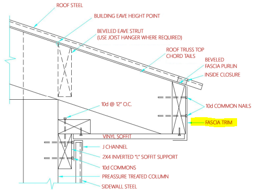
“Mike,  I have an existing pole barn (6×6 post with 2’ on center girts ) that has a 4” concrete floor with 10 mil plastic under it. The side walls have 1” XPS insulation on the outside of girt then steel siding with no wrap or barrier. My thought is put Tyvek on inside of girt ( facing same direction as if on outside application ) then put inch and a half XPS DOW insulation against that ( because there’s two bunks already there) then 2×4 frame with batten insulation between them, then 6mil or heavier vapor barrier then OSB. The floor has PEX tubing in it but not hooked up. Is this a proper install?  Also I will have to have an engineer check the BCDL as I want to put OSB on the ceiling but would like to know how to insulate the ceiling. There is a one foot fully vented overhang with a ridge vent also. Thank You for the info in advance. 

Mike the Pole Barn Guru advises:

I am concerned about your building having an inch of XPS insulation between girts and siding. This allows screw shanks to flex, potentially creating slotting under screw heads and excessive deformation can result in your building cladding’s shear strength being compromised and (under extreme circumstances) racking enough to create a failure. I would feel much more comfortable if you were to add 7/16″ OSB or 1/2″ CDX plywood to the inside of girts in bays on each side of corner columns from splash plank to eave girt.

Moving forward….

Your external XPS is now acting as a vapor barrier (or close to it). Any exposed to inside seams should be taped. Do not put Tyvek on the inside of the girts, as this would allow any moisture in assembly to be trapped between it and XPS. Unless you already own a pile of 1-1/2″ Dow insulation, skip it and instead fill the balance of the wall cavity with rock wool or stone wool unfaced batts. Do not place a vapor barrier on the inside or seal OSB on the inside of the wall. Walls will now ‘dry’ to inside.

Provided your trusses are capable of supporting a ceiling, blow in fiberglass above your ceiling finish of choice. Make sure to allow at least an inch of air space above insulation at eaves so you get proper air intake from vented soffits. Unless you are very close to Canada and have at least 8000 heating degree days, do not add a vapor barrier at ceiling level.

Nightmare From a Local Pole Building Contractor

Nightmare From a Local Pole Building Contractor

Reader RICK in OOLTEWAH writes:

Regrettably, after going with a local “pole building” contractor I find myself with a semi-completed building and a number of issues (I believe) to work through. The attached photos will hopefully help complete the picture. I was mostly ignorant of the pole building process, best practices, etc., instead just trusting the builder. I’m less ignorant now, thanks to your blog, but my timing could have been much better. I contracted to have a 30x40x12, to be used as a garage/machine shop, built on a leveled dirt pad, to be concreted later. After two months of waiting with said dirt pad ready, through several rainstorms, the contractor sent materials and a crew. They moved quickly, mostly getting the building up in a day. So quickly that no one noticed the standard trusses, not scissor as agreed upon. A 12′ overhead door (again stipulated) was not possible, and a 10’6″ went up in its place. This was a distraction until another hard rain showed water flow directly under the wall, highlighting what I think is the bigger issue. The splash plank has, in places, large gaps underneath (3-6″). By itself not so concerning, but for the fact there is no exposed splash plank on the exterior. The siding and edge trim is run to absolute bottom (nearly to grade). Meanwhile the doors float roughly 8 inches above grade/bottom edge of the trim/splash plank. This leaves a monstrous gap between the overhead when fully down and the highest the grade can go without backfilling against metal. Measurement inside shows exactly 12′ from the TOP of the splash plank to the bottom of the truss. They apparently zeroed out the build from the top of the plank, not the bottom, leaving the better part of 8 inches to make up for in the approach, fill and concrete, and a number of other areas. At this point the contractor has not called in a month, leaving off at “having a guy come install the cupola”. The silver lining for me thus far is I only have 1/3 of the money paid in. Given the way things have gone, I’m in no rush to give him any more, at least without being able to spell out what the problems and solutions are. I keep hoping Im still misunderstanding the process, and am seeing problems where there are none. But if that isn’t the case, what can be corrected and how?”

Mike the Pole Barn Guru says:

You are not alone, thousands of people, just like you, contract to have new buildings erected by “professional” building contractors, only to find what they thought they were getting and what they have received are two different animals. This is just one of many reasons why I encourage people to consider DIY instead – as an average physically able person who will read instructions often ends up with a much nicer finished product than what they would have paid for. If one lacks either time or ability to self-build, it is imperative to know fully what one has ordered and to literally camp out on site to verify work is done as agreed upon.

Hold on to your money tight until all issues are rectified. You do hold the ‘upper hand’ as your building has not been built as stipulated in your contract agreement – it does not have scissor trusses, nor a 12 foot tall overhead door. Rightfully, you could demand and it is likely a court would agree, for said building to be taken down and replaced with what you had ordered.

In order to reach a compromise solution, and provided you can get by with 11’3″ of height going through your overhead door, I would propose this:

Builder to add a 2×4 Pressure Preservative treated to UC-4A or better, below current splash plank.

Overhead door to be changed out to 11’3″ tall (as I can tell from your photos, it appears there is six inches from bottom of your building’s current splash plank to bottom of door).

Builder to fine grade interior to be even with bottom of newly installed treated 2×4.

Builder to grade exterior for 10 feet around building to slope at 5% from bottom of treated 2×4 outward away from building.

While this is not what you agreed upon, it may afford a practical solution to a nightmare you never should have had.

P.S. While crew is onsite, they should replace trim to right of your overhead door opening. Having a splice at this location is both unsightly and dangerous. They should also place a screw on both sides of every high rib of steel siding and roofing at both bottom and top ends of every panel (you will find this will then match manufacturer’s installation instructions).

How to Pour a Slab on Grade

How to Pour a Slab on Grade in an Existing Barndominium

Reader PAUL writes:

“I have an opportunity to purchase a barndominium that has the posts set in 20” wide 40” deep peers. Unfortunately the county where this is located does not require a footing. All city codes in this area require an 8”X 36” footing. What solutions do you recommend for pouring the slab now that the shell has been erected?”

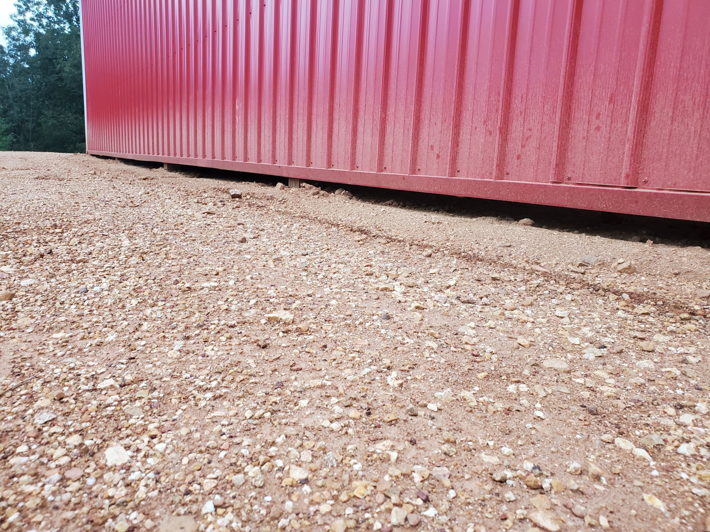
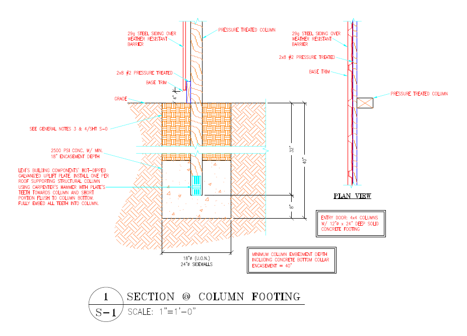
Most post frame buildings have shells erected then slab poured, so this should not be an issue. A pressure preservative treated splash plank should be in place around this building’s perimeter. It will become forms for your slab. Snap a chalk line on the inside of splash planks up 3-1/2″ from bottom, this will be top of your slab.

In Climate Zones other than 1 through 3, you will need to frost protect the building perimeter. This can be done by trenching around the edge of the building to required depth – 24″ in zones 4 and 5, 48″ in 6 and greater. It is usually easiest to install R-10 rigid insulation on the inside of the splash plank, with top of insulation even with top of slab to be poured. This also precludes any need to UV protect vertical insulation.

Depending upon how the site was prepared, you may need to excavate inside of this building. 

If in “frost country” a sub-base 6” or thicker should be first placed across the site. To maintain frost-free soils sub-base should be such as no more than 5% (by weight) will pass through a No. 200 sieve, and it is further desired no more than 2% be finer than .02 mm.

Prior to pouring, 2” to 6” of clean and drained sand or sandy gravel is spread below where concrete is to be poured. Mechanically compact fill to at least 90% of a Modified Proctor Density, otherwise slab could sink.

In areas prone to subterranean termites treat prepared soil with a termiticide barrier at a rate of one gallon of chemical solution per every 10 square feet.

Install a good, well-sealed 15mil vapor barrier below any interior pour, to stop moisture from traveling up into the slab through capillary action. Overlap all vapor barrier seams by a minimum of six inches, then tape. Vapor barrier should extend up column sides and to splash plank top. 

Minimum R-5 (R-10 being preferred) insulation shall be provided under full slab area of a heated slab in addition to required slab edge insulation R-value for slabs as indicated in International Energy Conservation Code (IECC) Table R402.1.2 Footnote (d).

In most instances, over properly compacted fill, 15 psi (pounds per square inch)  EPS (expanded polystyrene) or XPS (extruded polystyrene) insulation has adequate compressive strength to support a five yard dump truck on a nominal four inch slab on grade.

Consider this: 15 psi equals 2160 psf (pounds per square foot), making this greater than assumed compressive strength of most soil types.

If not using fiber-mesh or similar reinforcement additives to concrete mixture, place rebar (reinforcing steel rods) in slab center to add rigidity to concrete to aid in minimizing cracking.

Contractual Minimum Material Specifications

Disclaimer – this and subsequent articles on this subject are not intended to be legal advice, merely an example for discussions between you and your legal advisor.

Please keep in mind, many of these terms are applicable towards post frame building kits and would require edits for cases where a builder is providing erection services or materials and labor.

It never ceases to amaze me, when I read comments from people who have ordered a pole building kit, or a constructed building, and have little or no idea of how their building will go together, or what is or is not included. 

Wood Bending Strength
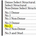
MINIMUM MATERIALS’ SPECIFICATIONS: (as applicable) Skirt Boards (splash planks): #2&btr pressure preservative treated to a minimum UC-4A specification. Structural Columns (those which support roof loads), pressure preservative treated to a minimum UC-4B specification. Spacing of wall columns is at Seller’s discretion unless specifically indicated on face of Agreement.

Wall Girts and Roof Purlins greater than 8′ in length, minimum #2&btr.

Prefabricated, engineered roof trusses, or rafters, at discretion of Seller, unless otherwise noted in the Agreement. On occasion, with sidewall overhangs, trusses may be shipped without tails – if so, appropriate lumber and hangers (as needed) will be furnished to field add overhangs. Lumber shall conform to the applicable grading agencies Standard Grading Rules. 

29 gauge steel roofing and siding. With steel roofing and siding and no sidewall overhangs, J Channel only shall be provided at tops of sidewalls as eave trim. No drip edge is included for steel roofing. Butyl tape sealant is supplied ONLY on roof steel overlaps for slopes of less than 3/12, unless by special order and indicated on face of invoice. 

Polycarbonate eave light panels are fastened with 1″ white screws nine inches on center. Ridge caps are fastened with roof steel colored stitch screws to each roofing high rib. 

Roof slope(s) not so specified in the Agreement are to be determined by Seller. Permanent roof truss chord bracing is as specified on third party E.O.R. sealed plans, which supersedes truss drawings. 

Sliding doors must be assembled on site, from provided components, will not seal airtight, do not include weather stripping and are not insulated. Sliding door jambs are ripped (by Purchaser) from Seller furnished 2×6 and are not pressure preservative treated as they are protected from weather when the door is closed.

Residential overhead doors may be approximately 2″ less in width and 1″ less in height than dimensions specified. Overhead door openings only are provided without vinyl weather seals. 

Pre-hung entry doors have 3-1/2″ jambs and may need to be installed swinging outward to facilitate full opening width. Doorknobs are usually positioned to be equidistant from top and bottom of doors. Seller is entitled to make substitutions of materials or equipment which Seller deems to be equivalent in performance to materials specified in the Agreement. 

At Seller’s option, roof radiant reflective barrier may be replaced by felt (or other similar barrier) over oriented strand board, without the need for a Change Order. When needed for shear wall requirements, Purchaser will not unduly prevent Seller from relocating any doors, windows, or other openings. 

Any shearwall or diaphragm blocking shall be as specified on third party E.O.R. sealed plans. Seller’s plans and instructions may deviate from component manufacturer’s installation instructions and manuals, due to judicious experience, and Purchaser acknowledges any such deviations are not cause for rejection or demands for extra or alternate materials.

Interior wall framing included only as specified on face of Agreement.

Eave height is the measure from the bottom of the pressure preservative treated skirt board (splash plank) (grade), to the underside of the roof steel (or other roofing material) at the outside of the sidewall double truss bearing columns. 

Interior clear height, allowing for a nominal four inch concrete floor, will be ten inches or more less than the eave height. It is the responsibility of Purchaser to determine if eave height, width and height of door openings, or provided doors, is adequate for Purchaser’s needs.

MINIMUM QUALITY SPECIFICATIONS: Steel roofing and siding may naturally dimple at through fasteners or ripple between supports, and as such, neither is a defect. Steel trims may be subject to oil canning, or other expansion and contraction conditions after installation – this is not a product defect. Although every good faith effort will be made, no guarantee is possible to exactly match any colors, to existing materials. Commercial overhead doors may be primed only, and as such, color variations and/or scratches are not defects.

PURCHASER SUPPLIED MATERIALS: Purchaser clearly understands Purchaser will under no circumstances be reimbursed for the purchase of any replacement materials for any reason (including suspected damage or shortage) without the prior written authorization of Seller, or Seller’s suppliers.

This one pertains specifically when a building is being erected by a contractor:

PURCHASER SUPPLIED LABOR: Any work performed by purchaser is strictly prohibited without Seller’s written consent, however Purchaser may supply his own labor, without adjustment of the agreement price, with the exception of the column holes “where applicable”. Should the Purchaser opt to excavate their own column holes, Seller will furnish Purchaser with a layout only, and Purchaser must properly locate the same. 

Column holes properly located, excavated and cleaned out by Purchaser, passing Building Department inspection will be credited at $10 per hole. For structures where columns are supported by brackets, purchaser to supply all equipment, and labor to properly embed into new concrete, except as otherwise noted. Purchaser is responsible for the timeliness and quality of all labor furnished by Purchaser, and is responsible for the performance of such work according to Seller’s schedule. Purchaser is responsible for Seller’s extra costs pursuant to section xx of this agreement, “change orders”, for extra costs incurred as a consequence of Purchaser’s failure to perform own labor in a timely manner without defect.

Avoiding Being Driven Crazy With Barndominium Questions Part II

Part II of a two part series. If you didn’t see Part I, go back one day.

Mike’s answers are in italics.

 In each house at ends of the “L” layout, I plan to have 1/3 open plan at two stories, for our great room, with nice windows for great views.

The other 2/3 areas will have 2 bedrooms and maybe a sitting area on the second floor.

  • Do  really need 6” * 6” poles in this area for the 2nd floor?
  • I was planning on building the upstairs like you do in a stick built house which would be use the 1st floor wall as load supporting, use 12” floor joists and  add a beam where needed and then use steel adjustable poles. (Cover poles later)
  • Is this OK to do?
  • Would the steel poles need to be on thicker concrete?
  • Would the 1st floor walls that will load support the 2nd floor need to be on thicker concrete?
  • You are free to say, “Greg if you had a decent floor plan, we should add a few poles, as it would be so much stronger, better, and other”.
  • Thoughts? Mike: Personally I would clearspan your second floor using prefabrciated wood floor trusses. There would be supported by LVL beams attached to your perimeter columns. This allows for walls to be placed anywhere without having to create bearing walls or have interior columns. All mechanicals can then be run through this floor truss system. If you were to approach your second floor as if it was traditional stick frame – you would then be faced with how to support it at exterior walls, since they are horizontally girted. Any bearing walls would have to have thicker concrete below and adjustable steel pole locations would probably require some sort of concrete pier (or at least slab being thicker and perhaps requiring some extra rebar). If using adjustable steel poles, I would want them to at least be wrapped with two layers of 5/8″ Type X sheetrock so in event of a fire they would not lose their temper, deform and collapse. 

Wall Girt System questions:

  • If the posts are 6” * 6” what width are the horizontal girt boards?  Are they 2” * 6” *  X’ or 2” * 8 “ * X’? Mike: For glulams of 2×6 you would have 2×8 girts, for 2×8 columns, 2×10 girts. These will project 1-1/2″ outside of your perimeter building columns.
  • If they are the 2 * 8’s, is there a little board you would put on the post, between the post and the outside metal? (This little stuff drives me crazy too!) Mike: Blocking would be placed on column exterior faces, aligned with wall girts to provide a continuous line for attaching steel siding with screws.
  • Are the vertical spacer boards nailed to the side of the post as shown on the attachment, so horizontal bookshelf girts can be nailed vertically into the spacer to avoid toe-nailing all of the girt boards? Mike: Bookshelf girts will be supported at each end with solid blocking against columns – no toe-nailing of girts to columns.

Does the lowest board on the posts, (Grade Board?), does it actually contact the dirt floor before pouring the floor? Mike: Bottom of pressure preservative treated grade board/splash plank is set at grade, so it is in contact with ground.

So the board will have 4” – 5” of cement contact? Mike: Top of your concrete slab would be 3-1/2 inches above bottom of splash plank.

How far does the siding cover the lowest board? Mike: Bottom edge of steel base trim drip leg will be at four inches above bottom of splash plank. This allows for any exterior concrete (walkways, approaches, door landings) to be poured against treated splash plank rather than against steel siding or trims.

Do you ever use a composite board for the grade board? Mike: Splash planks are used to transfer wind shear loads from siding to columns and into the ground. Composites are not structural and do not have an ability to transfer these loads.

Sorry for all the dumb questions. Mike: Only a question not asked would be considered as being dumb.

I appreciate all the effort from Hansen Pole Buildings.

Thanks

Top of Barndominium Slab

Where Should the Top of Barndominium Slab Be?

Loyal reader DANIEL in OWENSVILLE writes:

“Mike,

First I want to say thanks for all that I have learned from your Blog. I am confused on a couple of points you made concerning floor height…

“Occasionally we have clients who ask why they can’t run the concrete to the top of the splash plank, as they want to use the splash plank to “screed” the concrete slab top. Using any other measure for the concrete slab top, will result in wall steel and doors not properly fitting, as well as possible interior clear height loss.”

This really is not answering the question… the building could be designed with the door openings, ceiling heights, etc. to compensate for a higher floor height/thicker floor. Request it in the design and build it to the plan.

Also, “Your new Hansen Pole Building has as the bottom horizontal framing member, connecting pressure treated column to pressure treated column, is a pressure preservative treated splash plank. The building design is such so the top of any concrete floor is set at 3-1/2″ above the bottom of the splash plank.” and, In another post you stated the splash plank rests on the finished grade. That would put the finished concrete floor only 3-1/2″ above the finished grade. And below the weep screed, rat guard, any water being shed on the outside of the sheathing, and what codes require for an occupied building.

Please explain if there is any “real” reason for not raising the interior floor to 6 inches or more above grade (as is required for a house)?”

Daniel ~

Thank you for your kind words. Certainly any building could be designed for door openings, ceiling heights, etc., to be adjusted for top of slab on grade to be at any point. This would entail leaving greater amounts of splash plank exposed on exterior beneath siding in order to prevent concrete aprons, sidewalks, driveways, etc., from being poured up against wall steel. Some people find great amounts of splash plank being exposed to be aesthetically unpleasant however. By being consistent in design, it also allows for one set of assembly instructions to be used – rather than having to rely upon making adjustments for whatever custom situation individuals (or their builders) deemed their particular case.

I went back and read through both IRC (International Residential Code) and IBC (International Building Code) codes and there is no requirement for an interior concrete floor to be at six inches or more above grade for an occupied building or a house.

From 2018 IRC R506.1 “Concrete slab-on-ground floors shall be designed and constructed in accordance with the provisions of this section or ACI 332. Floors shall be a minimum 3-1/2 inches thick.”

From 2018 IBC 1907.1 “The thickness of concrete floor slabs supported directly on the ground shall not be less than 3-1/2”

Both of these imply top of concrete floor at 3-1/2″ above ground (grade) is totally acceptable. 

Having been involved in tens of thousands of post frame buildings successfully engineer designed and approved in structural plan reviews leads me to believe how we are doing it both works and is code conforming.

For extended reading on this subject: https://www.hansenpolebuildings.com/2016/05/concrete-floor/ and https://www.hansenpolebuildings.com/2012/02/where-is-the-top-of-the-concrete-slab/.

Planning for a Post Frame Home

When it comes to planning for a new post frame home, shouse (shop/house) or barndominium, there are a myriad of questions and concerns to be answered and pondered.

Or, at least I hope you are – rather than just stumbling in blindly!

Reader NICK in NORTH CAROLINA writes:

“Hi, I’m looking into options for building a post frame home in the coming year in NC and wanted to understand more of the details regarding your current building products and suggested techniques.  

Do you provide a means to support the posts on top of the concrete pillars with a bracket vs the post being embedded into the concrete?

Your current package only provides for insulation of the roof, no interior walls, correct?

Can another 2×6 skirt board be added to the inside of the building to isolate the concrete flooring from the post and to provide a cavity for insulation to be installed between the outside/inside girts?

Do you have a listing of contractors that are familiar with your products in given areas that could be used to build the structure?

If using the design service listed for $695, does that include the design for all interior walls/rooms/fixtures as well as electrical/plumbing/mechanical?

Thanks for any information you can provide.”

All good questions. In answer to them:

Yes we can provide plans with a third-party engineered design for bracket set columns, as well as brackets. https://www.hansenpolebuildings.com/2019/05/sturdi-wall-plus-concrete-brackets/

We typically recommend using either a Reflective Radiant Barrier (https://www.hansenpolebuildings.com/2017/05/effective-reflective-insulation/) between roof framing and roof steel, or using roof steel with factory applied Dripstop https://www.hansenpolebuildings.com/2012/11/drip-stop/

We can provide batt insulation for walls and/or ceilings, however there are more energy efficient methods of insulating https://www.hansenpolebuildings.com/2018/06/pole-barn-insulation-oh-so-confusing/

It (extra 2×6 interior splash plank) could, however there are structural advantages to having columns surrounded (constrained) on exterior splash plank interior. (https://www.hansenpolebuildings.com/2018/11/importance-of-constrained-posts/) I’d recommend doing a Frost Protected Shallow Foundation post frame style instead: https://www.hansenpolebuildings.com/2017/09/post-frame-frost-walls/

Although our buildings are designed for an average literate English speaking person to successfully construct their own building (most of them do, and do a wonderful job – because they will read and follow instructions), for those who do need an erector, in many areas we can provide contacts for you to vet.

Our floor plan and elevation package offer (http://www.hansenpolebuildings.com/post-frame-floor-plans/?fbclid=IwAR2ta5IFSxrltv5eAyBVmg-JUsoPfy9hbWtP86svOTPfG1q5pGmfhA7yd5Q)  includes all interior walls, rooms and fixtures. For an added fee you can include electrical/plumbing/mechanical (note: typically all of these last three services can usually be provided at no charge by subcontractors who will be doing these specific trades).

Please feel free to reach out to me at any time with questions. An answer to most questions can also be found at www.HansenPoleBuildings.com by clicking on SEARCH in the upper right hand corner of any page. Type in a word or two and hit ENTER and up pop relevant articles.

Avoiding Using Pressure Treated Wood

Avoiding Using Pressure Treated Wood

Pressure preservative treated wood remains a mainstay in modern wood construction. United States’ manufacturing and sales of pressure treated wood has become a multi-billion dollar industry. Even with all of this, there are some skeptics.

Reader DIANE in MORGANTOWN writes in:

“ I want to avoid pressure treated wood. Even the newer and safer versions. Can any alternate material be used? Concrete? Metal? Thank you!”

I personally have full faith in current formulations of pressure preservative treatment chemicals for wood to be both environmentally friendly, safe for myself and my loved ones, and to provide excellent longevity. With this being said everyone should do their own due diligence of any product and develop their own opinions based upon such research.

From 2015 IBC (International Building Code):

“2304.12.2.2 Posts or columns.

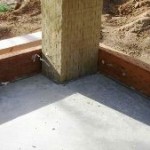
Posts or columns supporting permanent structures and supported by a concrete or masonry slab or flooring that is in direct contact with the earth shall be of naturally durable or preservative-treated wood.

Exception: Post or columns that are not exposed to the weather are supported by concrete piers or metal pedestals projected at least 1 inch (25mm) above the slab or deck and 8 inches (203 mm) above exposed earth and are separated by an impervious moisture barrier.”

Column holes can therefore be completely concrete filled with wet set brackets placed on top of concrete allowing use of untreated wood columns (as long as column isolated from concrete per Code or weather  protected, it does not have to be preservative treated). https://www.hansenpolebuildings.com/2012/09/concrete-brackets-2/

A splash plank will be required around post frame building base in order to provide a form for any concrete slab poured upon grade and/or to be an anchorage point for siding. Typically this a pressure treated 2×8. In your case, an untreated board of cedar or redwood could be used, as they are somewhat naturally decay resistant. I would recommend either be encased in a Plasti-skirt (https://www.hansenpolebuildings.com/2017/08/plasti-skirt/) as untreated cedar or redwood has a lifespan much shorter than treated wood.


Brick Ledge on a Pole Building

Brick Ledge on a Post Frame (Pole) Building

Whilst it would not be my personal preference for finish on a post frame building, there are instances when either aesthetics (trying to match other existing structures), local Planning Departments or HOAs (Home Owner Associations) mandate use of brick or stone exteriors. Whether for a wainscot or covering an entire wall (or walls) if full thickness stone or brick becomes a solution, it must be adequately structurally supported by a footing.

I truly had not given this subject much thought, until reader JASON in COLLEGE STATION wrote:

“Hello, thanks in advance for sharing some of your knowledge and experience with pole barns.

I have been looking at the construction details on your website and have a question about the bottom “skirt board”. Could this detail be designed so that the board does not show below the metal but the metal terminates on a concrete slab that extends a little? I am guessing this is how someone would do it if they needed a brick ledge. If so what is the best way to achieve this?

Thanks again for your advice.”

Jason’s question actually read like a multiple dilemma.

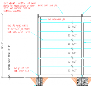
First, a question is hiding a building exterior pressure preservative treated skirt board (aka splash plank). Simple answer is yes, building is already designed so this can be done. Skirt board should be placed per engineer sealed building plans, showing drip edged base trim bottom four inches above grade. This allows for a nominal four inch thick (finished thickness 3-1/2”) sidewalk, driveway, landing or other concreted areas to be poured against exterior of splash plank, coming in ½ inch below bottom of drip edge. Any such pours should be along a grade sloping sufficiently away from building a minimum slope of 2%, to keep water from pooling against building.

For a nominal fee a RDP (Registered Design Professional – engineer or architect) can design an appropriate and structurally adequate support, varying in design due to individual building sites’ frost depths. Using a frost-protected shallow foundation in frost prone regions (read more here: https://www.hansenpolebuildings.com/2017/09/post-frame-frost-walls/), could possibly be part of a design solution, with some sort grade beam, whether it be poured reinforced concrete or properly pressure treated wood. Either will need to be engineered appropriately based upon material weight and strength of  soil to give continuous support.

I’d personally consider either thin brick, or a cultured stone veneer. Ultimately it will probably be least expensive design solution providing and meeting needed objectives. Framing, including columns and their embedment, will need to be engineered to support added dead loads from thin brick (depending upon pattern and thickness thin brick can weigh nearly seven pounds per square foot). Structural members need to be engineered to have limited deflection. Bookshelf girts might well be part of an engineered design solution: https://www.hansenpolebuildings.com/2011/09/commercial-girts-what-are-they/.


Installing Cement Panel Siding on a Pole Building

Installing Cement Panel Siding on Post Frame Buildings
Step 1
Install vertical cement siding over horizontal and vertical braced wood girts spaced a maximum of 24 inches on center. Alternatively, the panels can be installed over wood sheathing.

Step 2
Begin first panel with edge even with outside of corner column. If panel has overlap/underlap. begin with an overlapping edge. Fasten the panels to the sub-structure with a pneumatic nailer and corrosion-resistant nails. Drive the nails to be just flush with the surface of the panel, but not so deep the nails dimple the cement panel surface. Place all nails 3/8 inch from the panel edge and at least 2 inches from any corner.

Step 3
Ensure a bare minimum of six inches clearance up from grade to the panel bottom edge. Measure up from the six inch point on the splash plank the height of the cement panel siding at either end of the wall and snap a straight, level chalk line between the marks as a reference line. This line is for guidance in positioning the top edge of the panels. Check the reference line with a four foot level. Allow at least two inches of clearance between the material and any walkway paths, sidewalks, decking, stairs or driveways which can wick or leach water and chemicals into or out of the product.

Step 4
Starting on one end and working across the wall, measure and trim the first cement panel siding making sure the edge falls in the middle of a blocking member for support. Using the chalk line as a guide along the panel’s top edge, carefully position the panel and secure it with suitable fasteners and fastener spacing for the particular application. As installation continues, check the vertical edge of each cement panel siding with a four foot level. Leave an appropriate gap between panels (1/8 in is the most common) and do not jam panels up against one another, as this can cause warping over time.

Step 5
Caulk all cement panel siding joints with an elastomeric joint sealant which complies with ASTM C920 Grade NS, Class 25 or higher or a latex joint sealant complying with ASTM C834. Panels may be installed first with caulk applied in the joints after installation; or as an option, after the first panel is installed, apply a bead of caulk along the panel edge. When the next panel is installed against the first, the edge embeds in the applied caulk creating a thorough seal between the edges of the panels.

In some applications such as multi-story structures or at gable ends, it may be necessary to stack siding. The horizontal joints created between cement panels must be flashed properly to minimize water penetration. After installing the lower course of panel siding, install vinyl or coated aluminum “Z” flashing at the top edge of the panel. Make sure the flashing is sloped away from the wall and does not rest flat on the top edge of the panel. Install the second level or gable panels leaving a ¼ inch minimum gap between the bottom of the panel and the Z flashing. This gap should never be caulked.

The Case of the Termite Shields

When it comes to post frame building construction, I know a little bit about a lot of things. I get asked a lot of questions about how to solve post frame building challenges and do a pretty fair job of answering them. When I do not know an answer I feel confident in, I have no problems with doing the research or reaching out to an expert. Such was the “Case of The Termite Shields” (sound almost like a Sherlock Holmes story).

In this case, I went to “The Bug Doctor” Jerry Schappert of www.pestcemetery.com

Here was my question:

mr owl tootsie roll pop“We have a Building Official asking for a termite shield for a post frame (pole) building. The building utilizes pressure preservative treated columns embedded in the ground with a treated splash plank around the base of the walls. At the bottom of the steel wall siding is what is known as base trim, it is steel and extends outward from the splash plank 1-1/2″ with the outer edge being a downward bent lip. This should serve to function just like the steel termite shields we have viewed online. 4-5/8″ of the pressure preservative treated splash plank is visible below the base trim. There is a product called a plastiskirt which is vinyl and designed to wrap the splash plank. In your opinion, what would be the best design solution to protect the building from termites as well as to meet the requirements of the Building Code?”

The good doctor replied (in very short order I might note):

It sounds to me you’ve met the code already? What more does he or she want?  There are ‘pipe shields’ on the market but they are just basically what you describe. Pole barns here in Florida basically have very little code requirements and we are the termite capital of the world.  So without knowing what more the inspector is looking for I wouldn’t know how to answer.

Need a bug expert, try Jerry. Need a post frame building expert? I will give my best impression.


Miracle Truss Concerns

One of the great things about being the Pole Barn Guru is helping people who have construction challenges of all sorts – even those who do not have post frame buildings.

Here is a recent one:

Hi Pole Barn Guru, and thanks for your informative website and blog. I’m using email rather than the website question portal so I can include pictures. I’m a contractor, but my normal specialty is finish carpentry. I wouldn’t normally take on a pole building job, but this one is for my father so I’m helping him build it to try to save some money.

We’ve acquired a 51 x 120 ft building package made by Miracle Truss, a company which is apparently out of business, hence the lack of manufacturer support. The building was purchased years ago by a businessman who never put it up and finally decided to donate it to a church for a write-off. Long story short it eventually made its way to us, still palletized as new, for an incredible savings. So off the bat I’ll apologize for not buying a product from you, as we already have one. But I’m hoping I can use your expertise and perhaps do business in the future.

In case you’re unfamiliar with Miracle Truss, their design uses open-web steel trusses with owner-provided wood purlins and girts. Clips are welded to trusses to receive wood members. The design gives the strength and span benefits of metal with some of the economy of locally sourced lumber. It seems like a good design, but we’re still only in the planning & groundwork stages. The package includes Metal Sales siding and roofing.

My question relates to the use of “splash planks” on a metal-sided building. I know the purpose of the splash or skirt board in typical construction, but I’m doubting its necessity in this particular design. As you can see in the attached pictures, their plans call for a treated 2×6 splash plank which is used as the outside form board when pouring footings, with anchor bolts pre-installed, and then simply left in place and attached to the sill purlin. This places the outside plane of the wall 1-1/2″ outside of the concrete footing. There’s nothing wrong with this design of course, I just wonder if it’s necessary. I’m considering eliminating the permanent mud board, removing the concrete forms and using the sill (bottom) purlin to attach both the flashing and sheet. The last picture is a quick drawing of what I have in mind.

This means I would have to form my foundation 1-1/2″ outside of the stock plans, but save me 340 LF of AWW 2×6. Any thoughts on eliminating the outside splash board?

I’m also trying to decide the dimensions of my footings. Each post will sit over a buried Sonotube pier with a Bigfoot base, which will bear the weight of the building. The footing is really just a concrete”tie beam” and provides a sill for the walls, without really bearing anything. The total thickness of the wall is 17.5″ at the posts (our posts are W12″ I-beam, plus 5.5″ girt.), but only 5.5″ in between posts. I could form a continuous 17.5″ footing over the top of the Sonotubes (my original plan), or form an offset 8″ w footing to match the outside of the wall. I also am not sure how to choose footing thickness, since it’s not bearing. No guidelines are given for foundation in the package instructions, since climate makes a big difference. We are in southern Alaska, our code frost depth is 4 ft, which is where the tubes will sit. But I’m not sure what the footings should be. Any comments?

Thanks again for any advice you can give. I really appreciate the resources you offer. KADIN in KENAI

Dear Kadin:

Thank you for your kind words. We strive to be informative and entertaining.

IMPORTANT DISCLAIMER: The response below is only in regards to the now defunct Miracle Truss which produced the building package you now own. The Miracle Truss brand name is now held by Spider Steel Buildings, LLC. The current Miracle Truss was formed in 2015 and has no connection with the prior company or its products. According to their attorney, Kevin R. Coan of Hinshaw & Culbertson LLP, the current Miracle Truss can and does provide the lumber package as part of its services. Find out more about the new Miracle Truss at https://miracletruss.com/.

My objections to the defunct Miracle Truss system has always been how does one go about finishing the inside of the building with the steel frames in the way and (very important to most) the having to source one’s own lumber which can end up in a sticker shock situation.

Your Miracle Truss building’s outside 2×6 splash plank is there for a reason, and should be used. The bottom of it is the point at which level grade is on the exterior of your building. If it is not present the steel base trim will probably end up in contact with the ground outside of your building – which will result in premature deterioration as it slowly rusts away.

As to your footings, the best advice I can give would be to contract with a registered professional engineer in your area who can do an analysis of the forces upon your building, wind load, snow load, seismic, exposure, et. al. Also the engineer will need to take into account the bearing capacity of the soils at your site.

Good luck and let me know how it all turns out!
Mike the Pole Barn Guru

Lowe’s® on the Line

The phones ring at Hansen Pole Buildings every day from dawn-to-dusk, and sometimes both before and after. Some calls are a little more interesting than others.

Bright and early, first thing this morning Eric (one of the owners of Hansen Pole Buildings) gets a phone call from Lowe’s®.

Composite GradeboardIt seems Lowe’s® has a pole building contractor customer who really likes to use composite skirt boards. As Lowe’s® did not have a source, they started doing some research. It turns out the caller from Lowe’s® had read my article about them online (which prompted the call): https://www.hansenpolebuildings.com/blog/2013/08/composite-grade-board/

Eric and the gentleman from Lowe’s® had some friendly discussions about not only the composite skirt boards, but also in regards to the company which typically promotes and sells them. It seems the two of them were pretty much in agreement in their negative opinion using composite material for skirt boards.

The fun part of the conversation came later…after it was related to Eric how the builder (after sharing his love of composite skirt boards) proceeded to explain how he ran his interior liner steel to grade then filled it 4″ high with concrete on the steel ! Not only was the builder doing this, but he was proud of it!

For those readers who are unfamiliar with steel liner panels, they are most often used in the Midwest. The panels are typically the same profile as the steel roofing and siding. They are oftentimes very thin (sometimes even 30 gauge material) and feature low cost typically white polyester paint over a minimal galvanized or Galvalume® substrate.

Here is where things could get dicey for this particular builder.  Pre-painted Galvalume® sheets are not to come in contact with wet concrete. Concrete’s high alkalinity attacks aluminum in Galvalume, causing coating to peel. How would the builder know what the substrate was? He’d have to be asking who he purchased it from, and unless it was directly from the manufacturer, there is a good chance he won’t get the correct answer.

I am not a huge proponent of steel liner panels to begin with, but if I did have them in my building, I’d prefer the paint stayed on them!

Scratching my head, I am still trying to figure out why the builder is pouring against the liner….and can come up with only two things. The first is – it would save some concrete (between the liner panel and the skirt board). About a yard on an average 40’ x 60’ building. Of course the concrete savings would be offset, to a large part, by the extra four inches of steel liner panel around the entire perimeter.

The second reason….(and this is merely a guess) is the composite skirt boards may be too flexible to reliably pour against without bowing outward, or requiring a tremendous number of stakes to hold them in place.

Any ideas from the audience?  My wife, in a previous marriage, was married to a hog farmer – and she relates one of their buildings was done exactly like this – and why it was done that way. As happens in our “almost perfect” marriage, we don’t always agree – which is why I married her – we can “agree to disagree”.  Anyone else besides my lovely bride of 14 years have good reasons to run concrete over the bottom edge of horizontal interior steel panels?  Let me know!

Composite Grade Board

Typically post frame (pole) buildings have a pressure treated board at the base of all enclosed walls.

Composite GradeboardKnown also as a Bottom Girt, Grade Girt, Skirt Board or Splash Plank, it is a decay and corrosion resistant girt which is in soil contact or located near the soil surface. It remains visible from the building exterior upon building completion, and is normally two inches in nominal thickness.

A decade ago, after CCA (Chromated Copper Arsenate) pressure treating went by the wayside, many splash planks were treated with ACQ (Alkaline Copper Quaternary). When water was introduced into connections between ACQ pressure treated lumber and steel, a chemical reaction occurred, which could quickly corrode steel siding and fasteners. For the most part, ACQ treated lumber is now rarely used, having been replaced by chemicals which do not interact corrosively with steel.

In efficient post frame construction, building components are positioned and connected in such a way to form a diaphragm. The gradeboard is an integral component of a properly designed shear wall (diaphragm) assembly. Structural wall sheathing (most commonly plywood, oriented strand board or corrugated steel) is attached to the gradeboard by sheathing-to-framing connectors which are located at the bottom edge of the structural sheathing panels.

The sheathing-to-framing connectors must be adequate in size, strength and resistance to pull out to be able to transfer shear loads, which are induced into the building by wind or seismic events, from the sheathing into the gradeboard. Similarly, the gradeboard must be attached to the columns at each end sufficiently to transfer the load.

At one time I had read a posting online, which downplayed the structural significance of gradeboards. In my mind, they are a key and important structural member.

Touted as an alternative to the traditional pressure treated lumber skirt board, is the composite grade board. Manufactured in a fashion similar to composite decking, they eliminate any risk of corrosion, rotting or decay.

The composite grade board features a built-in bottom ledge, which eliminates the need for a steel bottom trim (also known as base trim or “rat guard”).

Composite grade boards expand and contract dramatically with temperature fluctuations. As such, potentially unsightly gaps must be left at each end. For a 60 degree temperature fluctuation, a 3/16” gap is required (based upon a 16’ piece).

One of the “benefits” of the composite grade board is supposed to be price. I recently did a price comparison and found 2×8 #2 and better pressure treated at 97 cents per foot, while the composite grade board from the very same retailer was $2.99 per foot (over three times the cost)!

Having used composite materials for decks and stairs, I’ve found composites to not nearly have the strength of the lumber they are replacing. Furthermore, composites seem to allow a great deal of “give” around fasteners. When loaded in a shearwall assembly, I would have great concerns about fasteners pulling through composite grade boards.

The IBC (International Building Code) gives specifics in tables for shearwall construction, none of which include an approval for use of composite materials rather than dimensional lumber framing. Alternative materials are allowed to be utilized outside of the prescriptive portions of the Code, however testing documentation to prove structural adequacy should be provided.

Me…without some actual proven test results, there is no way on earth I would structurally use, or recommend the use of, a composite grade board.


Where is the Top of the Concrete Slab?

This is not like Where’s Waldo?, or Where in the World is Carmen San Diego?

The relationship of the top of a concrete slab inside your new pole building, to the grade surrounding the building is critical not only during construction, but also in the lifetime of performance of your building.

Hansen Pole Buildings services pole building kit package clients for several major lumber yard chains. One of them kindly provided us with a set of the building plans they had been supplying to their everyday client base. As I began to review the plans, I was astounded to find the building was designed so any concrete floor being poured had the top of the slab even with the grade outside of the building.

In the event of a rainstorm, or heavy snow melt, water would easily coming pour into the building!

Your new Hansen Pole Building has as the bottom horizontal framing member, connecting pressure treated column to pressure treated column, is a pressure preservative treated splash plank. The building design is such so the top of any concrete floor is set at 3-1/2” above the bottom of the splash plank.

On the outside of your building, assuming it is steel sided, the base trim (also known as rat guard), is installed so the lowest point of the drip edge is four inches above grade. This allows for any concrete driveway approaches or doorway aprons to be poured appropriately in relationship to the top of the level of the interior slab. It also keeps any exterior concrete from being poured against steel trims or siding.

While proper jobsite preparation and compaction of fill beneath a concrete floor has more to do with the performance of the slab than does thickness, some clients want floors thicker than the typical nominal four (3-1/2” actual) inches. If a thicker floor is desired, excavate below skirt board bottom, by any slab thickness greater than 4”. In no case, will the top of the concrete floor be even with either the top or bottom of the splash plank.

Occasionally we have clients who ask why they can’t run the concrete to the top of the splash plank, as they want to use the splash plank to “screed” the concrete slab top.   Using any other measure for the concrete slab top, will result in wall steel and doors not properly fitting, as well as possible interior clear height loss.

TIP:  If you want to use a board for screeding the concrete slab, take a 2×4 pressure treated board and nail it to the inside of the splash plank with the bottom of the 2×4 even with the bottom of the splash plank.  This board stays concreted in around the perimeter of your concrete slab.  Quick.  Easy.  And ensures a level concrete slab, at just the right height.